Cirkit Designer
Your all-in-one circuit design IDE
Home /
Project Documentation
ESP32 and Ultrasonic Sensor-Based Wi-Fi Controlled Robotic Car
Circuit Documentation
Summary
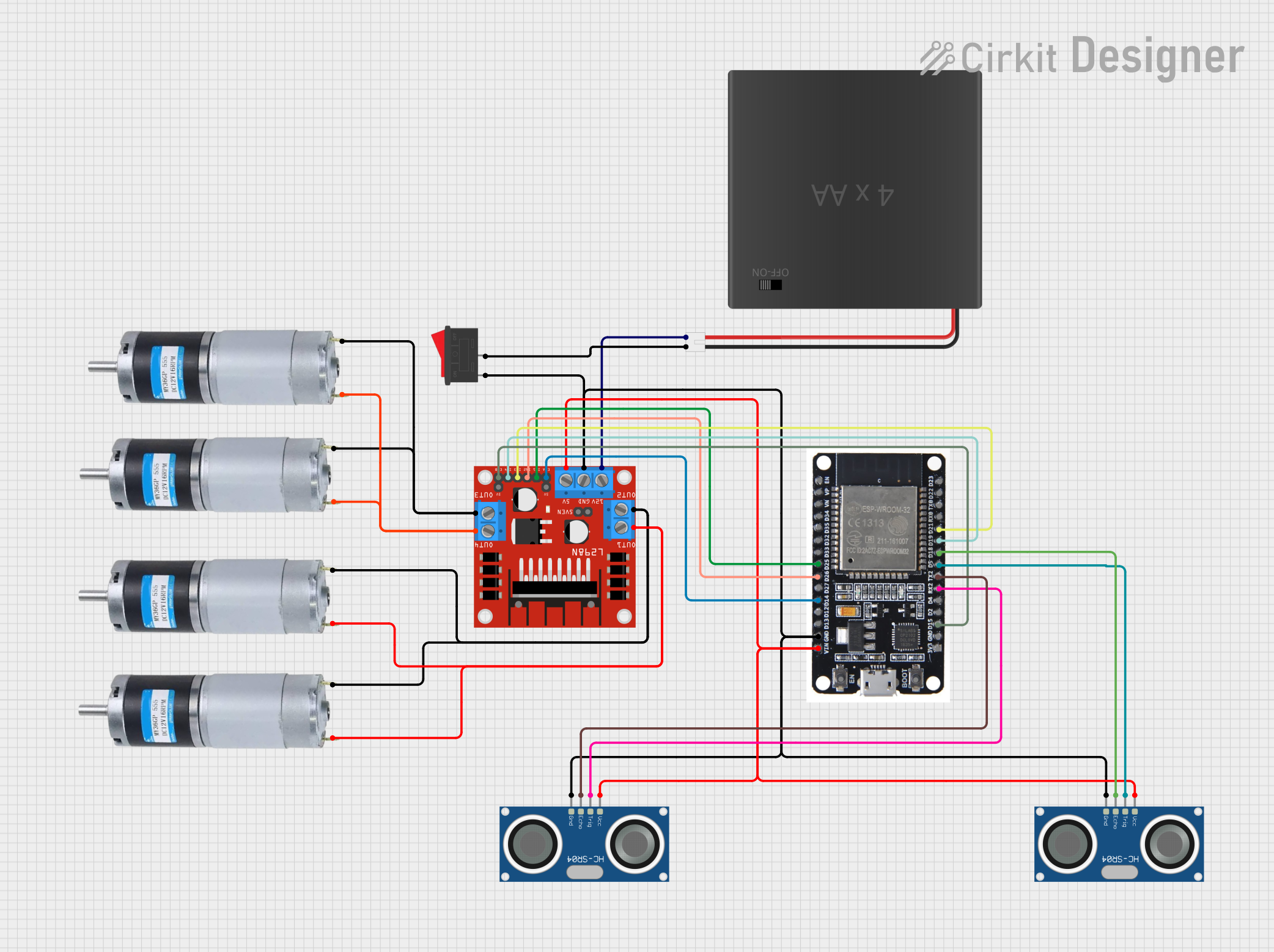
This document provides a detailed overview of a circuit that includes an ESP32 microcontroller, an L298N DC motor driver, two HC-SR04 ultrasonic sensors, multiple DC motors, a rocker switch, and a 4xAA battery pack. The circuit is designed to control DC motors and read distance measurements from ultrasonic sensors, with the ESP32 serving as the central control unit.
Component List
HC-SR04 Ultrasonic Sensor
- Description: Ultrasonic distance sensor
- Pins: VCC, TRIG, ECHO, GND
L298N DC Motor Driver
- Description: Dual H-Bridge motor driver
- Pins: OUT1, OUT2, 12V, GND, 5V, OUT3, OUT4, 5V-ENA-JMP-I, 5V-ENA-JMP-O, +5V-J1, +5V-J2, ENA, IN1, IN2, IN3, IN4, ENB
ESP32
- Description: Microcontroller with Wi-Fi and Bluetooth capabilities
- Pins: EN, VP, VN, D34, D35, D32, D33, D25, D26, D27, D14, D12, D13, GND, VIN, 3V3, D15, D2, D4, RX2, TX2, D5, D18, D19, D21, RX0, TX0, D22, D23, BOOT
DC Motor
- Description: Standard DC motor
- Pins: positive, negative
Rocker Switch
- Description: On/Off switch
- Pins: 1, 2
4xAA Battery Pack
- Description: Battery pack with JST connector
- Pins: POS, NEG
Wiring Details
HC-SR04 Ultrasonic Sensor (1)
- VCC: Connected to 5V of L298N DC motor driver
- TRIG: Connected to D5 of ESP32
- ECHO: Connected to D18 of ESP32
- GND: Connected to GND of L298N DC motor driver, GND of ESP32, and GND of Rocker Switch
HC-SR04 Ultrasonic Sensor (2)
- VCC: Connected to 5V of L298N DC motor driver
- TRIG: Connected to RX2 of ESP32
- ECHO: Connected to TX2 of ESP32
- GND: Connected to GND of L298N DC motor driver, GND of ESP32, and GND of Rocker Switch
L298N DC Motor Driver
- IN1: Connected to D25 of ESP32
- IN2: Connected to D26 of ESP32
- ENA: Connected to D14 of ESP32
- GND: Connected to GND of HC-SR04 Ultrasonic Sensor (1), GND of ESP32, and GND of Rocker Switch
- 5V: Connected to VCC of HC-SR04 Ultrasonic Sensor (1), VIN of ESP32, and VCC of HC-SR04 Ultrasonic Sensor (2)
- ENB: Connected to D15 of ESP32
- IN4: Connected to D19 of ESP32
- IN3: Connected to D21 of ESP32
- 12V: Connected to POS of 4xAA Battery Pack
- OUT1: Connected to positive of DC Motor (1)
- OUT2: Connected to negative of DC Motor (1)
- OUT3: Connected to negative of DC Motor (2)
- OUT4: Connected to positive of DC Motor (2)
ESP32
- D25: Connected to IN1 of L298N DC motor driver
- D26: Connected to IN2 of L298N DC motor driver
- D14: Connected to ENA of L298N DC motor driver
- GND: Connected to GND of L298N DC motor driver, GND of HC-SR04 Ultrasonic Sensor (1), and GND of Rocker Switch
- VIN: Connected to 5V of L298N DC motor driver
- D15: Connected to ENB of L298N DC motor driver
- RX2: Connected to TRIG of HC-SR04 Ultrasonic Sensor (2)
- TX2: Connected to ECHO of HC-SR04 Ultrasonic Sensor (2)
- D5: Connected to TRIG of HC-SR04 Ultrasonic Sensor (1)
- D18: Connected to ECHO of HC-SR04 Ultrasonic Sensor (1)
- D19: Connected to IN4 of L298N DC motor driver
- D21: Connected to IN3 of L298N DC motor driver
DC Motor (1)
- positive: Connected to OUT1 of L298N DC motor driver
- negative: Connected to OUT2 of L298N DC motor driver
DC Motor (2)
- positive: Connected to OUT4 of L298N DC motor driver
- negative: Connected to OUT3 of L298N DC motor driver
Rocker Switch
- 1: Connected to GND of L298N DC motor driver, GND of HC-SR04 Ultrasonic Sensor (1), and GND of ESP32
- 2: Connected to NEG of 4xAA Battery Pack
4xAA Battery Pack
- POS: Connected to 12V of L298N DC motor driver
- NEG: Connected to 2 of Rocker Switch
Code
No code provided for this circuit.
This document provides a comprehensive overview of the circuit, including a summary, component list, wiring details, and code section. Each component is described, and its connections are detailed to ensure clarity and ease of understanding.