
Arduino 101 Controlled Robotic Arm with VL53L1X Distance Sensor
View and Edit Project In Cirkit Designer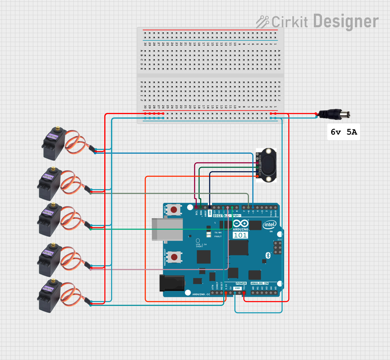
Circuit Documentation
Summary
This document provides a detailed overview of a circuit that includes an Arduino 101 microcontroller, a VL53L1X distance sensor, multiple MG996R servo motors, and a power jack. The circuit is designed to interface the Arduino 101 with the distance sensor and control several servo motors. The power jack supplies the necessary power to the components.
Component List
Arduino 101
- Description: A microcontroller board based on the Intel Curie module.
- Pins: A5/SCL, A4/SDA, AREF, GND, D13/SCK, D12/MISO, D11 PWM/MOSI, D10 PWM/SS, D9 PWM, D8, D7, D6 PWM, D5 PWM, D4, D3 PWM, D2, D1/TX, D0/RX, AIN, ioref, RESET, 3V3, 5V, VIN, A0, A1, A2, A3, ICSP MISO, ICSP SCK, ICSP MOSI
VL53L1X
- Description: A time-of-flight distance sensor.
- Pins: VIN, GND, SDA, SCL, INT, SHUT
MG996R
- Description: A high-torque servo motor.
- Pins: GND, VCC, SIG
Power Jack
- Description: A power jack for supplying power to the circuit.
- Pins: POSITIF, NEGATIF
Wiring Details
Arduino 101
- 3V3 connected to VL53L1X VIN
- GND connected to VL53L1X GND, MG996R GND (all instances), and Power Jack NEGATIF
- A4/SDA connected to VL53L1X SDA
- A5/SCL connected to VL53L1X SCL
- VIN connected to MG996R VCC (all instances) and Power Jack POSITIF
- D6 PWM connected to MG996R SIG (first instance)
- D11 PWM/MOSI connected to MG996R SIG (second instance)
- D10 PWM/SS connected to MG996R SIG (third instance)
- D9 PWM connected to MG996R SIG (fourth instance)
- D5 PWM connected to MG996R SIG (fifth instance)
VL53L1X
- VIN connected to Arduino 101 3V3
- GND connected to Arduino 101 GND
- SDA connected to Arduino 101 A4/SDA
- SCL connected to Arduino 101 A5/SCL
MG996R (First Instance)
- GND connected to Arduino 101 GND
- VCC connected to Arduino 101 VIN
- SIG connected to Arduino 101 D6 PWM
MG996R (Second Instance)
- GND connected to Arduino 101 GND
- VCC connected to Arduino 101 VIN
- SIG connected to Arduino 101 D11 PWM/MOSI
MG996R (Third Instance)
- GND connected to Arduino 101 GND
- VCC connected to Arduino 101 VIN
- SIG connected to Arduino 101 D10 PWM/SS
MG996R (Fourth Instance)
- GND connected to Arduino 101 GND
- VCC connected to Arduino 101 VIN
- SIG connected to Arduino 101 D9 PWM
MG996R (Fifth Instance)
- GND connected to Arduino 101 GND
- VCC connected to Arduino 101 VIN
- SIG connected to Arduino 101 D5 PWM
Power Jack
- POSITIF connected to Arduino 101 VIN and MG996R VCC (all instances)
- NEGATIF connected to Arduino 101 GND and MG996R GND (all instances)
Code
No code is provided for this circuit.
This document provides a comprehensive overview of the circuit, including a summary, component list, wiring details, and code section. The wiring details ensure that each component is correctly connected to the Arduino 101 and power jack, facilitating proper operation of the circuit.