
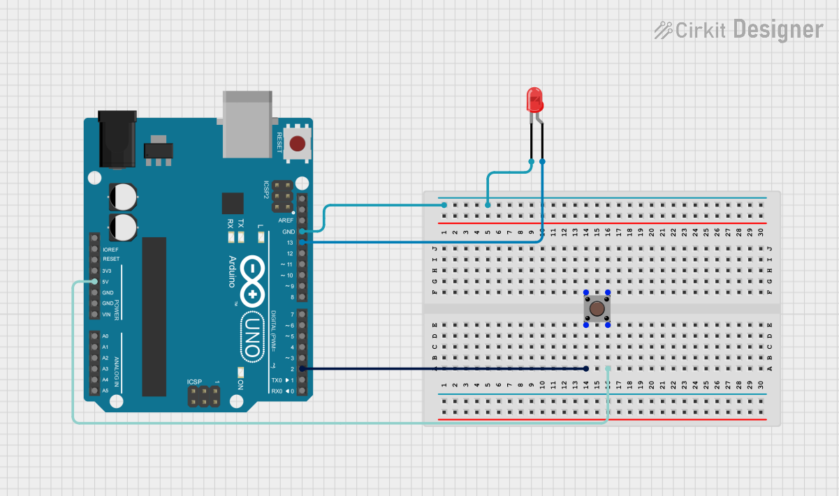
Circuit Documentation
Summary
This circuit consists of an Arduino UNO microcontroller, a pushbutton, and a red LED. The pushbutton is used to control the LED. When the button is pressed, the LED turns on, and when the button is released, the LED turns off.
Component List
Arduino UNO
- Description: A microcontroller board based on the ATmega328P.
- Pins: UNUSED, IOREF, Reset, 3.3V, 5V, GND, Vin, A0, A1, A2, A3, A4, A5, SCL, SDA, AREF, D13, D12, D11, D10, D9, D8, D7, D6, D5, D4, D3, D2, D1, D0
Pushbutton
- Description: A simple pushbutton switch.
- Pins: Pin 3 (out), Pin 4 (out), Pin 1 (in), Pin 2 (in)
LED: Two Pin (red)
- Description: A red LED with two pins.
- Pins: cathode, anode
Wiring Details
Arduino UNO
- D2: Connected to Pin 2 (in) of the Pushbutton
- 5V: Connected to Pin 4 (out) of the Pushbutton
- GND: Connected to cathode of the LED
- D13: Connected to anode of the LED
Pushbutton
- Pin 2 (in): Connected to D2 of the Arduino UNO
- Pin 4 (out): Connected to 5V of the Arduino UNO
LED: Two Pin (red)
- cathode: Connected to GND of the Arduino UNO
- anode: Connected to D13 of the Arduino UNO
Code Documentation
/*
 * This Arduino sketch controls a green LED using a button with a pull-down
 * resistor configuration. When the button is pressed, the LED will turn on.
 * When the button is released, the LED will turn off.
 */

const int buttonPin = 2; // Pin connected to the button
const int ledPin = 13;   // Pin connected to the green LED

void setup() {
  pinMode(buttonPin, INPUT); // Set button pin as input
  pinMode(ledPin, OUTPUT);   // Set LED pin as output
}

void loop() {
  int buttonState = digitalRead(buttonPin); // Read the state of the button
  if (buttonState == HIGH) {
    digitalWrite(ledPin, HIGH); // Turn the LED on
  } else {
    digitalWrite(ledPin, LOW);  // Turn the LED off
  }
}
This code initializes the button pin as an input and the LED pin as an output. In the main loop, it reads the state of the button and turns the LED on or off based on the button's state.