
Circuit Documentation
Summary of the Circuit
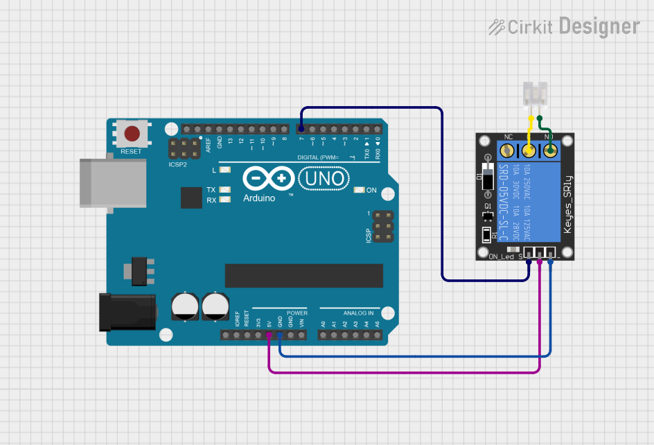
This circuit consists of an Arduino UNO microcontroller, a 1-Channel Relay module (5V 10A), and a JST PH 2.0 connector. The Arduino UNO is used as the central control unit, capable of interfacing with various sensors, actuators, and other modules. The 1-Channel Relay module is used to control high power devices, allowing the low-power Arduino to safely control larger loads. The JST PH 2.0 connector serves as an interface for external connections.
Component List
Arduino UNO
- Description: A microcontroller board based on the ATmega328P.
- Pins: UNUSED, IOREF, Reset, 3.3V, 5V, GND, Vin, A0-A5, SCL, SDA, AREF, D0-D13.
1-Channel Relay (5V 10A)
- Description: A relay module capable of switching up to 10A of current at 5V.
- Pins: NC (Normally Closed), signal, C (Common), power, NO (Normally Open), ground.
JST PH 2.0 connector
- Description: A 2-pin connector commonly used for battery and peripheral connections.
- Pins: 1, 2.
Wiring Details
Arduino UNO
- 5V: Provides power to the relay module.
- GND: Common ground with the relay module.
- D7: Digital output to control the relay signal.
1-Channel Relay (5V 10A)
- power: Connected to the 5V output from the Arduino UNO.
- ground: Connected to the GND on the Arduino UNO.
- signal: Controlled by the D7 pin on the Arduino UNO.
- C (Common): Connected to pin 2 of the JST PH 2.0 connector.
- NO (Normally Open): Connected to pin 1 of the JST PH 2.0 connector.
JST PH 2.0 connector
- Pin 1: Connected to the NO (Normally Open) pin of the relay module.
- Pin 2: Connected to the C (Common) pin of the relay module.
Documented Code
Arduino UNO Code (sketch.ino)
void setup() {
  // put your setup code here, to run once:

}

void loop() {
  // put your main code here, to run repeatedly:

}
The provided code is a template with empty setup() and loop() functions. The setup() function is intended for initialization code that runs once when the Arduino is powered on or reset. The loop() function contains the main logic of the program, which runs repeatedly as long as the Arduino is powered.
Additional Notes
- The code for the Arduino UNO is currently a placeholder and needs to be populated with the logic to control the relay module via the D7 pin.
- The relay module's signal pin should be driven HIGH to activate the relay and connect the common (C) to the normally open (NO) contact, allowing current to flow to the device connected to the JST PH 2.0 connector.
- Safety precautions should be taken when dealing with high power devices connected to the relay.