
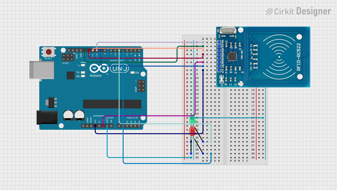
Circuit Documentation
Summary
The circuit in question is designed around an Arduino UNO microcontroller and includes an RFID-RC522 module for RFID communication, as well as two LEDs (one green and one red) for status indication. The RFID module is interfaced with the Arduino UNO via SPI (Serial Peripheral Interface), and the LEDs are connected to digital pins for simple on/off control. The circuit is likely intended for applications requiring RFID tag reading with visual status indicators.
Component List
Arduino UNO
- Description: A microcontroller board based on the ATmega328P.
- Pins Used: IOREF, Reset, 3.3V, 5V, GND, Vin, A0-A5, SCL, SDA, AREF, D0-D13.
- Purpose: Acts as the central processing unit of the circuit, controlling the RFID module and LEDs.
RFID-RC522
- Description: An RFID reader/writer module.
- Pins Used: VCC (3.3V), RST, GND, IRQ, MISO, MOSI, SCK, SDA.
- Purpose: To read RFID tags and communicate with the Arduino UNO.
LED: Two Pin (green)
- Description: A basic green LED.
- Pins Used: cathode, anode.
- Purpose: To serve as a visual indicator, likely for successful RFID tag reads.
LED: Two Pin (red)
- Description: A basic red LED.
- Pins Used: cathode, anode.
- Purpose: To serve as a visual indicator, likely for error or unsuccessful RFID tag reads.
Wiring Details
Arduino UNO
- D10: Connected to RFID-RC522 SDA.
- D13: Connected to RFID-RC522 SCK.
- D11: Connected to RFID-RC522 MOSI.
- D12: Connected to RFID-RC522 MISO.
- GND: Connected to RFID-RC522 GND, green LED cathode, and red LED cathode.
- D9: Connected to RFID-RC522 RST.
- 3.3V: Connected to RFID-RC522 VCC (3.3V).
- D5: Connected to green LED anode.
- D4: Connected to red LED anode.
RFID-RC522
- SDA: Connected to Arduino UNO D10.
- SCK: Connected to Arduino UNO D13.
- MOSI: Connected to Arduino UNO D11.
- MISO: Connected to Arduino UNO D12.
- GND: Connected to Arduino UNO GND.
- RST: Connected to Arduino UNO D9.
- VCC (3.3V): Connected to Arduino UNO 3.3V.
LED: Two Pin (green)
- Anode: Connected to Arduino UNO D5.
- Cathode: Connected to Arduino UNO GND.
LED: Two Pin (red)
- Anode: Connected to Arduino UNO D4.
- Cathode: Connected to Arduino UNO GND.
Documented Code
Arduino UNO Code (sketch.ino)
void setup() {
  // put your setup code here, to run once:

}

void loop() {
  // put your main code here, to run repeatedly:

}
Note: The provided code is a template and does not include specific functionality. It needs to be populated with the logic for interfacing with the RFID-RC522 module and controlling the LEDs based on the RFID tag reads.