
Arduino UNO with NRF24L01 Wireless Communication and Analog Input Control
View and Edit Project In Cirkit Designer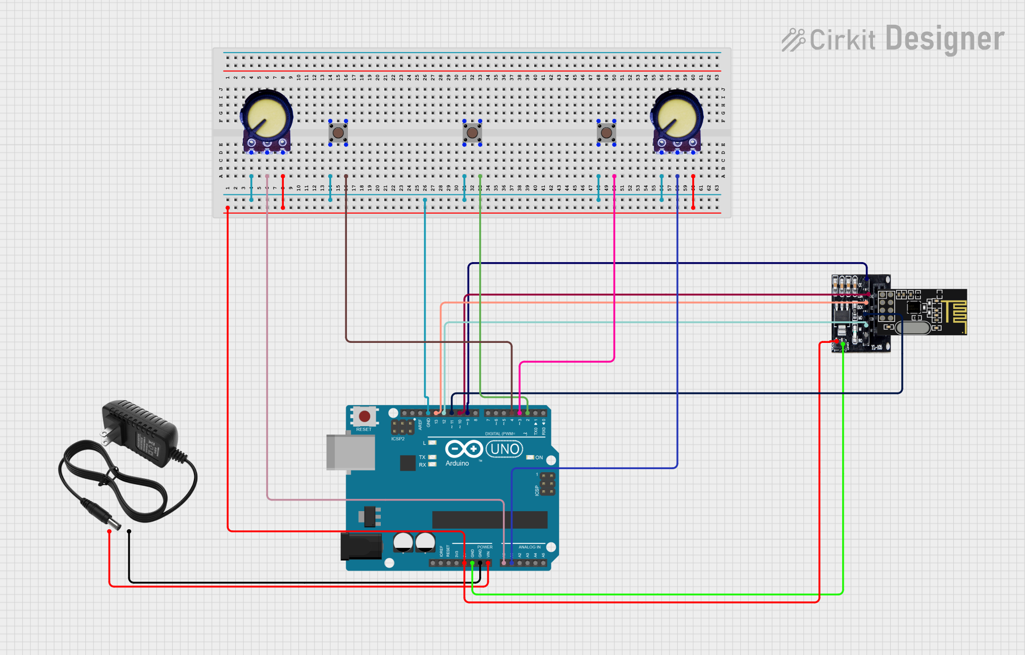
Circuit Documentation
Summary
This document provides a detailed overview of a circuit that includes an Arduino UNO as the main microcontroller, interfaced with an NRF24L01 module through an adapter, powered by a 12V power supply. The circuit also includes two potentiometers and three pushbuttons. The Arduino UNO is responsible for managing the inputs from the potentiometers and pushbuttons and communicating with the NRF24L01 module for potential wireless communication.
Component List
Arduino UNO
- Microcontroller board based on the ATmega328P
- It has 14 digital input/output pins, 6 analog inputs, a 16 MHz quartz crystal, a USB connection, a power jack, an ICSP header, and a reset button.
NRF24L01 Adapter
- An adapter module for NRF24L01 wireless transceiver module
- Provides regulated power and breaks out the pins of the NRF24L01 module.
12V Power Supply
- Provides the necessary power to the circuit
- Outputs a 12V supply which is stepped down by the Arduino to power the circuit.
NRF24L01
- A wireless transceiver module
- Operates in the 2.4 GHz band and can be used for wireless communication between devices.
Potentiometer (x2)
- A three-terminal resistor with a sliding or rotating contact that forms an adjustable voltage divider.
- Used for varying input to the Arduino analog pins.
Pushbutton (x3)
- A simple switch mechanism for controlling some aspect of a machine or a process.
- Buttons are typically used to provide user input to the Arduino.
Wiring Details
Arduino UNO
- 5V connected to NRF24L01 Adapter VCC, Potentiometer VCC (x2)
- GND connected to NRF24L01 Adapter GND, 12V Power Supply -, Potentiometer GND (x2), Pushbutton Pin 2 (in) (x3)
- Vin connected to 12V Power Supply +
- A0 connected to Potentiometer Output (1st instance)
- A1 connected to Potentiometer Output (2nd instance)
- D2 connected to Pushbutton Pin 4 (out) (3rd instance)
- D3 connected to Pushbutton Pin 4 (out) (2nd instance)
- D4 connected to Pushbutton Pin 4 (out) (1st instance)
- D9 connected to NRF24L01 Adapter CE
- D10 connected to NRF24L01 Adapter CSN
- D11 connected to NRF24L01 Adapter MOSI
- D12 connected to NRF24L01 Adapter MISO
- D13 connected to NRF24L01 Adapter SCK
NRF24L01 Adapter
- VCC connected to Arduino UNO 5V
- GND connected to Arduino UNO GND
- CE connected to Arduino UNO D9
- CSN connected to Arduino UNO D10
- SCK connected to Arduino UNO D13
- MOSI connected to Arduino UNO D11
- MISO connected to Arduino UNO D12
12V Power Supply
- + connected to Arduino UNO Vin
- - connected to Arduino UNO GND
Potentiometer (x2)
- VCC connected to Arduino UNO 5V
- Output connected to Arduino UNO A0 (1st instance) and A1 (2nd instance)
- GND connected to Arduino UNO GND
Pushbutton (x3)
- Pin 4 (out) connected to Arduino UNO D4 (1st instance), D3 (2nd instance), D2 (3rd instance)
- Pin 2 (in) connected to Arduino UNO GND
Documented Code
Arduino UNO Code (sketch.ino)
void setup() {
  // put your setup code here, to run once:

}

void loop() {
  // put your main code here, to run repeatedly:

}
Additional Notes
- The provided code is a template and does not include any functionality. It needs to be populated with the logic for reading the potentiometers and pushbuttons, as well as for controlling the NRF24L01 module.
- The
setup()function is used for initializing settings, and theloop()function runs continuously, allowing the Arduino to perform operations based on the inputs from the potentiometers and pushbuttons, and to communicate with the NRF24L01 module. - The actual implementation of the code will depend on the specific requirements of the circuit's application.