
Wi-Fi Controlled RFID Access System with LED Indicators and Buzzer
View and Edit Project In Cirkit Designer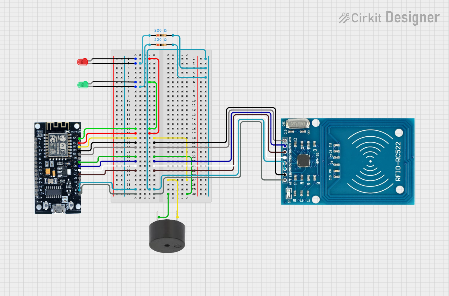
Circuit Documentation
Summary
This document provides a detailed overview of a circuit that includes an ESP8266 microcontroller, a red and green LED, a buzzer, two resistors, and an RFID-RC522 module. The circuit is designed to control the LEDs and buzzer based on inputs from the RFID module, with the ESP8266 serving as the central controller.
Component List
ESP8266
- Description: A low-cost Wi-Fi microchip with full TCP/IP stack and microcontroller capability.
- Pins: 3V, G, D8, D7, D6, D5, D4, D3, D2, D1, D0, A0, S3, S2, S1, SC, S0, SK, EN, VIN, RST, VU
LED: Two Pin (red)
- Description: A red light-emitting diode.
- Pins: cathode, anode
LED: Two Pin (green)
- Description: A green light-emitting diode.
- Pins: cathode, anode
Buzzer
- Description: An audio signaling device.
- Pins: PIN, GND
Resistor (220 Ohms)
- Description: A resistor with a resistance of 220 Ohms.
- Pins: pin1, pin2
RFID-RC522
- Description: A low-cost RFID module that operates at 13.56 MHz.
- Pins: VCC (3.3V), RST, GND, IRQ, MISO, MOSI, SCK, SDA
Wiring Details
ESP8266
- D1 is connected to the anode of the red LED.
- D0 is connected to the anode of the green LED.
- D2 is connected to the PIN of the buzzer.
- D3 is connected to the RST of the RFID-RC522.
- D4 is connected to the SDA of the RFID-RC522.
- D5 is connected to the SCK of the RFID-RC522.
- D6 is connected to the MISO of the RFID-RC522.
- D7 is connected to the MOSI of the RFID-RC522.
- G is connected to the GND of the buzzer and the GND of the RFID-RC522.
- 3V is connected to the VCC (3.3V) of the RFID-RC522.
LED: Two Pin (red)
- anode is connected to D1 of the ESP8266.
- cathode is connected to pin1 of a 220 Ohm resistor.
LED: Two Pin (green)
- anode is connected to D0 of the ESP8266.
- cathode is connected to pin1 of a 220 Ohm resistor.
Buzzer
- PIN is connected to D2 of the ESP8266.
- GND is connected to G of the ESP8266.
Resistor (220 Ohms)
- pin1 of one resistor is connected to the cathode of the red LED.
- pin2 of the same resistor is connected to G of the ESP8266.
- pin1 of the other resistor is connected to the cathode of the green LED.
- pin2 of the same resistor is connected to G of the ESP8266.
RFID-RC522
- RST is connected to D3 of the ESP8266.
- SDA is connected to D4 of the ESP8266.
- SCK is connected to D5 of the ESP8266.
- MISO is connected to D6 of the ESP8266.
- MOSI is connected to D7 of the ESP8266.
- GND is connected to G of the ESP8266.
- VCC (3.3V) is connected to 3V of the ESP8266.
Code
No code is provided for this circuit.