Touch-Interactive Distance Measurement System with Visual and Audio Feedback
Circuit Documentation
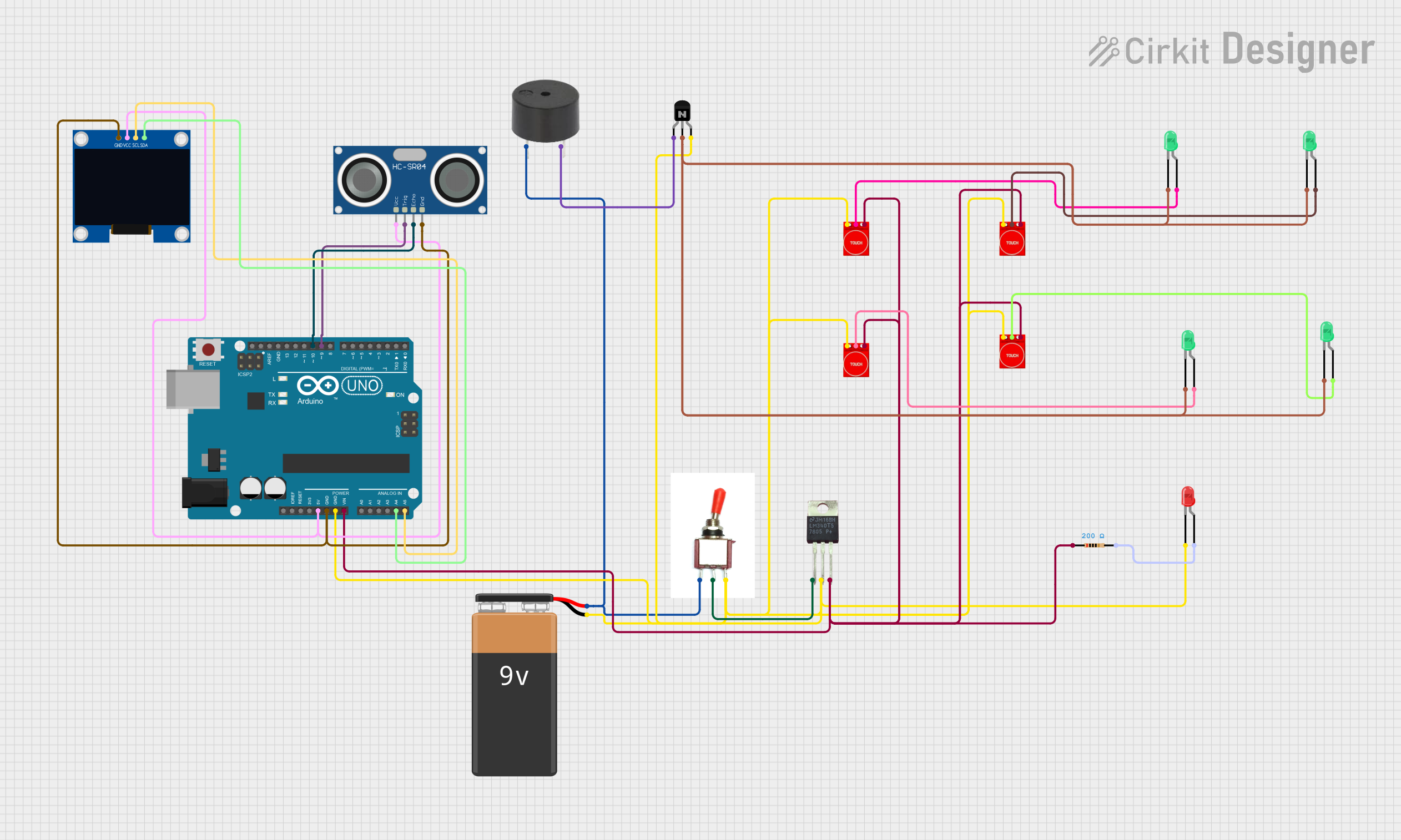
Summary of the Circuit
This circuit appears to be a control and sensing system that utilizes an Arduino UNO as the central processing unit. It includes a 9V battery for power, a toggle switch to control power flow, a voltage regulator (LM340T5 7805) to provide a stable 5V output, multiple touch sensors (TTP233) for user input, green and red LEDs for visual output, an NPN transistor to drive the LEDs, a buzzer for audio output, a resistor to limit current through the red LED, an HC-SR04 ultrasonic sensor for distance measurement, and a 128x64 OLED display for visual data output.
Component List
- 9V Battery: Provides the power source for the circuit.
- Toggle Switch: Controls the power supply to the circuit components.
- LM340T5 7805 (Voltage Regulator): Regulates the input voltage to a stable 5V output.
- Touch Sensor TTP233: Capacitive touch sensors used for user input.
- LED (Green): Visual indicators that can be controlled by the touch sensors.
- LED (Red): A visual indicator, typically used for status or warning signals.
- NPN Transistor (CBE): Acts as a switch to control the current flow through the LEDs.
- Buzzer: Provides audio feedback or alerts.
- Resistor (200 Ohms): Limits the current through the red LED to prevent damage.
- Arduino UNO: The microcontroller board that controls the circuit's logic and processing.
- HC-SR04 Ultrasonic Sensor: Measures distances by emitting ultrasonic waves and measuring the time taken for the echo to return.
- 128x64 OLED Display (I2C IIC SPI Serial): Displays information and data visually.
Wiring Details
9V Battery
- Negative terminal connected to the ground net of the circuit.
- Positive terminal connected to the input of the toggle switch.
Toggle Switch
- Vcc pin connected to the positive terminal of the 9V battery.
- Sig pin connected to the input of the voltage regulator (LM340T5 7805).
- Gnd pin connected to the ground net of the circuit.
LM340T5 7805 (Voltage Regulator)
- Vin pin connected to the Sig pin of the toggle switch.
- Vout pin provides a regulated 5V output to the Arduino UNO, touch sensors, and the ultrasonic sensor.
- GND pin connected to the ground net of the circuit.
Touch Sensor TTP233
- GND pin connected to the ground net of the circuit.
- I/O pin connected to the anode of the corresponding green LED.
- VCC pin connected to the 5V output from the voltage regulator.
LED (Green)
- Cathode pin connected to the ground net through the NPN transistor.
- Anode pin connected to the I/O pin of the corresponding touch sensor TTP233.
LED (Red)
- Cathode pin connected to the ground net of the circuit.
- Anode pin connected to one end of the resistor (200 Ohms).
NPN Transistor (CBE)
- Emitter pin connected to the ground net of the circuit.
- Base pin connected to the cathodes of the green LEDs.
- Collector pin connected to the buzzer's GND pin.
Buzzer
- PIN connected to the positive terminal of the 9V battery through the toggle switch.
- GND pin connected to the collector of the NPN transistor.
Resistor (200 Ohms)
- One pin connected to the anode of the red LED.
- The other pin connected to the 5V output from the voltage regulator.
Arduino UNO
- GND pin connected to the ground net of the circuit.
- Vin pin connected to the 5V output from the voltage regulator.
- 5V pin provides power to the OLED display and the ultrasonic sensor.
- A4 (SDA) and A5 (SCL) pins connected to the SDA and SCL pins of the OLED display, respectively.
- D9 and D10 pins connected to the TRIG and ECHO pins of the ultrasonic sensor, respectively.
HC-SR04 Ultrasonic Sensor
- VCC pin connected to the 5V pin of the Arduino UNO.
- TRIG pin connected to the D9 pin of the Arduino UNO.
- ECHO pin connected to the D10 pin of the Arduino UNO.
- GND pin connected to the ground net of the circuit.
128x64 OLED Display (I2C IIC SPI Serial)
- GND pin connected to the ground net of the circuit.
- SDA pin connected to the A4 (SDA) pin of the Arduino UNO.
- SCL pin connected to the A5 (SCL) pin of the Arduino UNO.
- VCC pin connected to the 5V pin of the Arduino UNO.
Documented Code
void setup() {
  // put your setup code here, to run once:

}

void loop() {
  // put your main code here, to run repeatedly:

}
The provided code is a template with empty setup() and loop() functions, which are the standard structure for Arduino sketches. The setup() function is intended to contain initialization code that runs once when the microcontroller is powered on or reset. The loop() function is intended to contain the main logic of the program, which runs repeatedly as long as the microcontroller is powered. Additional code is required to control the components as per the circuit design.