Cirkit Designer
Your all-in-one circuit design IDE
Home /
Project Documentation
Raspberry Pi and Arduino Mega Controlled Stepper Motor System with Limit Switches and Sensors
Circuit Documentation
Summary
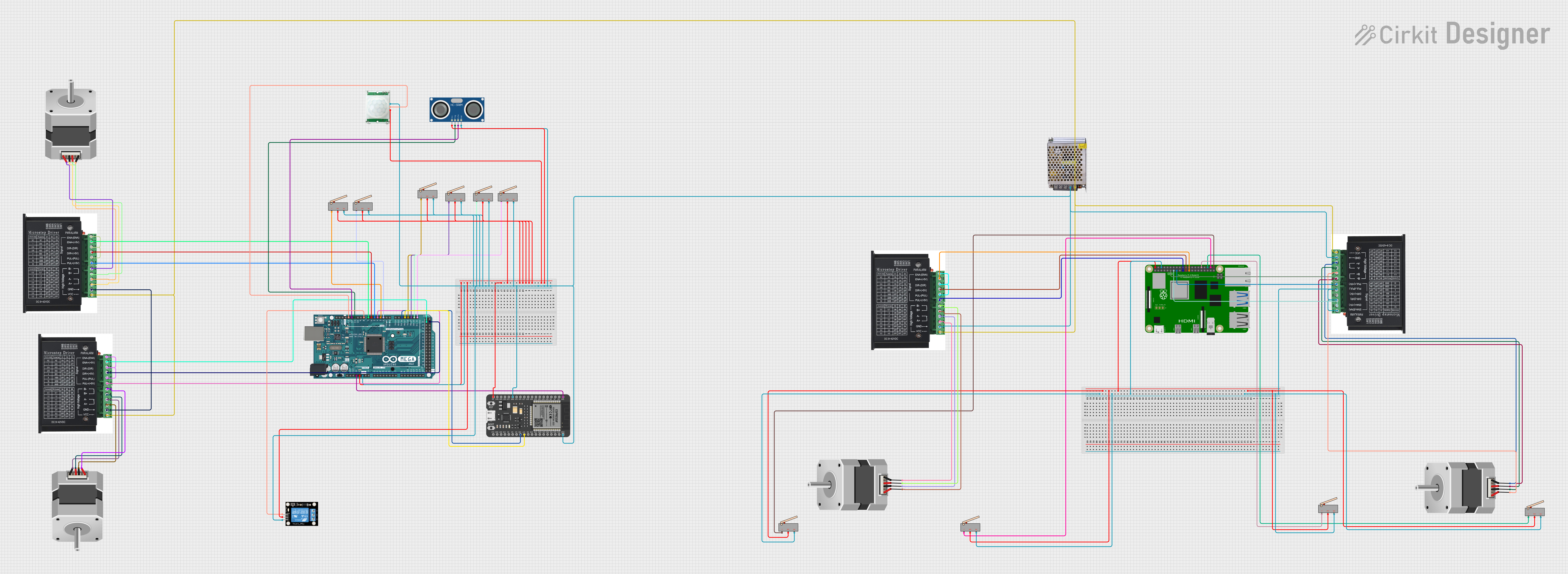
This document provides a detailed overview of a circuit designed to control stepper motors, read from sensors, and manage power distribution. The circuit includes a Raspberry Pi 4B as the main controller, an Arduino Mega 2560 and an ESP32 for additional control and interfacing, stepper drivers for motor control, limit switches for position sensing, a power supply, and various sensors and a relay for input and output operations.
Component List
Raspberry Pi 4B
- A microcomputer with multiple GPIO pins used for controlling the stepper drivers and interfacing with limit switches.
Arduino Mega 2560
- A microcontroller board based on the ATmega2560, with numerous digital and analog I/O pins.
ESP32 - 38 pins
- A microcontroller with Wi-Fi and Bluetooth capabilities, used for additional control and interfacing.
Limit Switch (x8)
- A switch that is actuated by the motion of a machine part or presence of an object, used for position sensing.
STEPPER DRIVER (x4)
- A device that drives a stepper motor based on input control signals.
POWER SUPPLY 12V 5AMP
- Provides a 12V DC power output to the stepper drivers and other components.
Stepper Motor (Bipolar) (x4)
- A type of stepper motor with two coils, controlled by the stepper drivers.
HC-SR04 Ultrasonic Sensor
- A sensor that measures distance by emitting ultrasonic waves and measuring the time taken for the echo to return.
PIR/Motion Sensor
- A sensor that detects motion based on changes in infrared radiation levels.
Relay module 1 channel
- An electrically operated switch that allows control of a high-power circuit with a low-power signal.
Wiring Details
Raspberry Pi 4B
- GPIO17 connected to DIR+ on a STEPPER DRIVER
- GPIO27 connected to ENA+ on a STEPPER DRIVER
- GPIO22 connected to PUL+ on a STEPPER DRIVER
- GPIO10 connected to PUL+ on another STEPPER DRIVER
- GPIO9 connected to DIR+ on another STEPPER DRIVER
- GPIO11 connected to ENA+ on another STEPPER DRIVER
- GPIO12, GPIO16, GPIO20, GPIO21 connected to C on different Limit Switches
- 5V connected to NO on multiple Limit Switches
- GND connected to NC on multiple Limit Switches
Arduino Mega 2560
- 3V3 connected to 3V3 on ESP32
- D21/SCL, D20/SDA, D19/RX1, D18/TX1, D2 PWM, D3 PWM connected to C on different Limit Switches
- D17 PWM/RX2, D16 PWM/TX2 connected to G17, G16 on ESP32
- D4 PWM, D5 PWM, D6 PWM, D7 PWM, D8 PWM, D11 PWM, D12 PWM, D13 PWM, D22, D23 connected to various STEPPER DRIVER signals and sensors
- 5V connected to VCC on various sensors and relay module
- GND connected to GND on various components
ESP32 - 38 pins
- GND connected to GND on various components
- 5V connected to VCC on various components
- G17, G16 connected to D17 PWM/RX2, D16 PWM/TX2 on Arduino Mega 2560
Limit Switches
- C connected to various control pins on Raspberry Pi 4B and Arduino Mega 2560
- NO connected to 5V on Raspberry Pi 4B
- NC connected to GND on Raspberry Pi 4B
STEPPER DRIVER
- ENA-, DIR-, PUL- connected to GND
- ENA+, DIR+, PUL+ connected to control signals from Raspberry Pi 4B or Arduino Mega 2560
- B-, B+, A-, A+ connected to corresponding pins on Stepper Motors
- VCC connected to 12V-24V Output (DC) from POWER SUPPLY 12V 5AMP
- GND connected to GND on various components
POWER SUPPLY 12V 5AMP
- 12V-24V Output (DC) connected to VCC on STEPPER DRIVERs
Stepper Motors (Bipolar)
- A, B, C, D connected to corresponding pins on STEPPER DRIVERs
HC-SR04 Ultrasonic Sensor
- VCC connected to 5V on Arduino Mega 2560
- TRIG connected to D11 PWM on Arduino Mega 2560
- ECHO connected to D12 PWM on Arduino Mega 2560
- GND connected to GND on Arduino Mega 2560
PIR/Motion Sensor
- VCC connected to 5V on Arduino Mega 2560
- OUTPUT connected to D13 PWM on Arduino Mega 2560
- GND connected to GND on Arduino Mega 2560
Relay module 1 channel
- S connected to D8 PWM on Arduino Mega 2560
- 5V connected to 5V on Arduino Mega 2560
- GND connected to GND on Arduino Mega 2560
Documented Code
Arduino Mega 2560 Code (sketch.ino)
void setup() {
  // put your setup code here, to run once:

}

void loop() {
  // put your main code here, to run repeatedly:

}
Note: The provided code for the Arduino Mega 2560 is a template with empty setup and loop functions. This code should be populated with the logic required to control the connected components based on the wiring details provided.