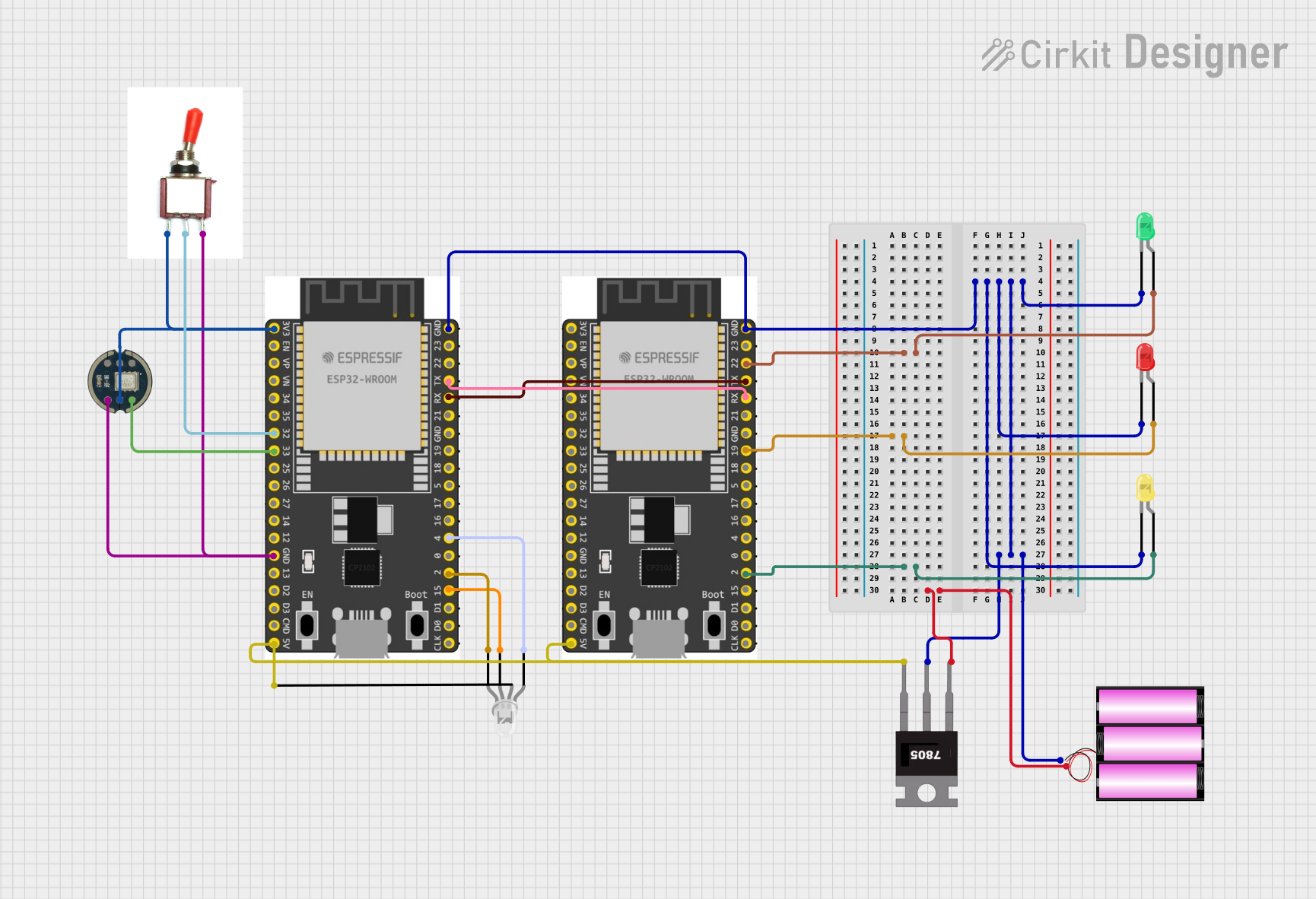
ESP32-Powered Voice-Controlled LED Lighting System

Circuit Documentation
Summary
The circuit in question appears to be a microcontroller-based system designed to control various LEDs and interface with an INMP441 microphone. The system uses two ESP32 Wroom Dev Kits as the main processing units, a 7805 voltage regulator to step down the voltage from a 12V battery, and a toggle switch to control power flow. The ESP32 microcontrollers are programmed to control the state of the LEDs and communicate with each other via serial communication. The INMP441 is connected to one of the ESP32s for audio input purposes.
Component List
Microcontrollers
- ESP 32 Wroom Dev Kit: A powerful microcontroller with Wi-Fi and Bluetooth capabilities, equipped with multiple GPIOs for interfacing with other components.
Sensors
- INMP441: A high-performance, low power, digital output, omnidirectional MEMS microphone with an I2S interface.
Power Supply
- Battery 12V: Provides the power source for the circuit.
- 7805 Voltage Regulator: Steps down the voltage from 12V to 5V for components requiring lower voltage.
Switches
- Toggle Switch: A simple on-off switch to control the power flow in the circuit.
Indicators
- LED: Two Pin (green, yellow, red): Basic LEDs used as visual indicators.
- LED: Four Pin: An RGB LED capable of displaying multiple colors.
Wiring Details
ESP 32 Wroom Dev Kit
- GND: Connected to the ground plane of the circuit.
- GPIO Pins: Various GPIO pins are used to control the LEDs and interface with the INMP441 microphone and the toggle switch.
- 3V3: Powers the INMP441 microphone.
- V5: Connected to the output of the 7805 voltage regulator to power the RGB LED.
- RXD/TXD: Used for serial communication between the two ESP32 microcontrollers.
INMP441
- VDD: Powered by the 3.3V output from one of the ESP32 microcontrollers.
- SD: Connected to a GPIO pin on the ESP32 for data transfer.
- GND: Connected to the ground plane of the circuit.
Toggle Switch
- Vcc: Connected to the 3.3V output from the ESP32.
- Sig: Connected to a GPIO pin on the ESP32 to detect switch state.
- Gnd: Connected to the ground plane of the circuit.
LEDs (Two Pin and Four Pin)
- Anode (common anode for RGB LED): Connected to the positive voltage supply (5V from the 7805 regulator for the RGB LED).
- Cathode: Connected to various GPIO pins on the ESP32 microcontrollers to control the LED states.
7805 Voltage Regulator
- Vin: Connected to the positive terminal of the 12V battery.
- Gnd: Connected to the ground plane of the circuit.
- Vout: Provides a regulated 5V output to power the ESP32 microcontrollers and the RGB LED.
Battery 12V
- +: Connected to the Vin pin of the 7805 voltage regulator.
- -: Connected to the ground plane of the circuit.
Documented Code
ESP 32 Wroom Dev Kit (Primary Controller)
//////Running code with board manager version 1.0.6
#define led_1 15
#define led_2 4
#define button 32 // Button_Sensor
#define led_3 2
#define RXp2 16
#define TXp2 17
#include "Audio.h"
#include "CloudSpeechClient.h"
int i=0;
void setup() {
  pinMode(button, INPUT);
  pinMode(led_1, OUTPUT);
  pinMode(led_2, OUTPUT);
  pinMode(led_3, OUTPUT);
  Serial.begin(115200);
  Serial2.begin(115200, SERIAL_8N1, RXp2, TXp2);
  //  Serial.println(My_Data);
}

void loop() {
  digitalWrite(led_1, 0);
  digitalWrite(led_2, 0);
  digitalWrite(led_3, 0);

  if(i==0){
    Serial.println("Press button");
    i=1;
  }
  delay(500);
  if(digitalRead(button)==0){
    Serial2.println("\nPlease Ask!\n");
    digitalWrite(led_1, 1);
    digitalWrite(led_2, 0);
    digitalWrite(led_3, 0);
    delay(2100);

    Serial.println("\r\nRecord start!\r\n");
    Audio* audio = new Audio(ADMP441);
    audio->Record();
    Serial.println("Recording Completed Processing");
    digitalWrite(led_1, 0);
    digitalWrite(led_3, 0);
    digitalWrite(led_2, 1);
    CloudSpeechClient* cloudSpeechClient = new CloudSpeechClient(USE_APIKEY);
    cloudSpeechClient->Transcribe(audio);
    delete cloudSpeechClient;
    delete audio;
    i=0;
  }
  if(digitalRead(button)==1){
    delay(1000);
  }
}
ESP 32 Wroom Dev Kit (Secondary Controller)
#define pin_1 2  // Pin for light one control
#define pin_2 22  // Pin for light two control
#define pin_3 19  // Pin for light three control

void setup() {
    pinMode(pin_1, OUTPUT);
    pinMode(pin_2, OUTPUT);
    pinMode(pin_3, OUTPUT);
    Serial.begin(115200);
    Serial2.begin(115200);
}

void loop() {
    if (Serial2.available()) {
        String receivedText = Serial2.readString();
        Serial.println("Received text: " + receivedText);
        processCommand(receivedText);
    }
    delay(100);
}

void processCommand(String command) {
    command.toLowerCase(); // Convert to lowercase for easier matching

    // Light one control
    if (command.indexOf("turn on light one") >= 0) {
        digitalWrite(pin_1, HIGH);  // Set pin_1 HIGH (1)
        Serial.println("Pin 1 set HIGH");
    } else if (command.indexOf("turn off light one") >= 0) {
        digitalWrite(pin_1, LOW);   // Set pin_1 LOW (0)
        Serial.println("Pin 1 set LOW");
    }

    // Light two control
    else if (command.indexOf("turn on light two") >= 0) {
        digitalWrite(pin_2, HIGH);  // Set pin_2 HIGH (1)
        Serial.println("Pin 2 set HIGH");
    } else if (command.indexOf("turn off light two") >= 0) {
        digitalWrite(pin_2, LOW);   // Set pin_2 LOW (0)
        Serial.println("Pin 2 set LOW");
    }

    // Light three control
    else if (command.indexOf("turn on light three") >= 0) {
        digitalWrite(pin_3, HIGH);  // Set pin_3 HIGH (1)
        Serial.println("Pin 3 set HIGH");
    } else if (command.indexOf("turn off light three") >= 0) {
        digitalWrite(pin_3, LOW);   // Set pin_3 LOW (0)
        Serial.println("Pin 3 set LOW");
    }

    // All lights control
    else if (command.indexOf("turn on all lights") >= 0) {
        digitalWrite(pin_1, HIGH);
        digitalWrite(pin_2, HIGH);
        digitalWrite(pin_3, HIGH);
        Serial.println("All pins set HIGH");
    } else if (command.indexOf("turn off all lights") >= 0) {
        digitalWrite(pin_1, LOW);
        digitalWrite(pin_2, LOW);
        digitalWrite(pin_3, LOW);
        Serial.println("All pins set LOW");
    }

    else {
        Serial.println("Command not recognized");
    }
}
Note: The code for the 7805 voltage regulator is a placeholder and does not contain any functional code. It is assumed that the regulator does not require programming and operates based on its electrical characteristics.