ESP32-Based Safety and Tracking System with GSM and GPS
Circuit Documentation
Summary
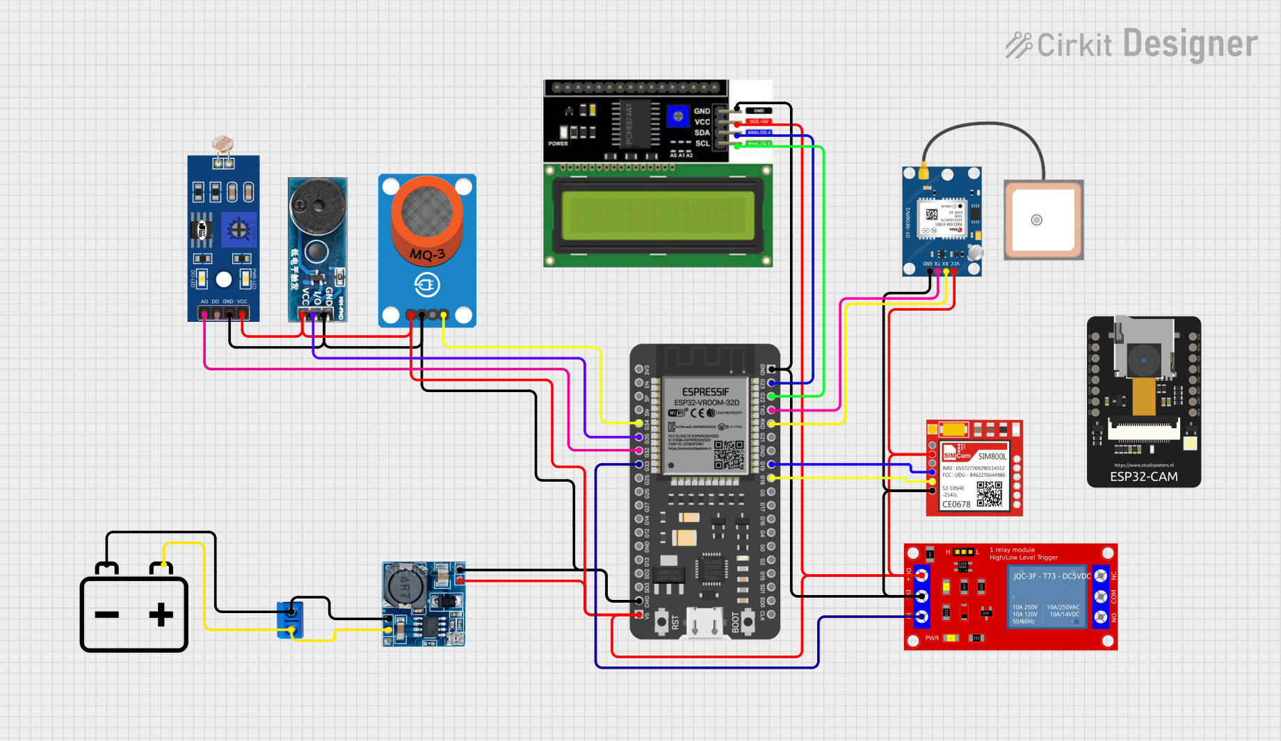
The circuit in question appears to be a multifunctional system incorporating various sensors, communication modules, and a microcontroller. The central component of the circuit is an ESP32 microcontroller, which interfaces with a range of peripherals including an MQ-3 alcohol sensor, a buzzer module, a light-dependent resistor (LDR), a 5V relay module, an LCD display with I2C interface, a SIM800L GSM module, and a GPS NEO 6M module. Power management is handled by a step-down module that converts 12V input to 5V output, and a 12V battery provides the power source. The circuit is designed for monitoring, data acquisition, and communication purposes.
Component List
12v Battery
- Description: Provides the power source for the circuit.
ESP32 - 38 pins
- Description: A microcontroller with Wi-Fi and Bluetooth capabilities, serving as the central processing unit of the circuit.
Step down Module
- Description: Converts the 12V input from the battery to a 5V output used by various components in the circuit.
Terminal PCB 2 Pin
- Description: A simple two-pin terminal used for connecting the battery to the step-down module.
1 Channel 5V Relay Module
- Description: An electromechanical switch that allows the ESP32 to control high power devices.
MQ-3 Breakout
- Description: A gas sensor module for detecting alcohol vapors in the air.
Buzzer Module
- Description: An audio signaling device that can be controlled by the ESP32.
LCD I2C Display
- Description: A display module with an I2C interface for showing information.
LDR
- Description: A light-dependent resistor that changes resistance based on light intensity.
Sim800l
- Description: A GSM/GPRS module that allows the circuit to communicate over cellular networks.
GPS NEO 6M
- Description: A GPS module for obtaining geographical location data.
ESP32 - CAM
- Description: A camera module that can be used for capturing images and video.
Wiring Details
12v Battery
-connected to Terminal PCB 2 Pin (Pin B) and Step down Module (GND)+connected to Terminal PCB 2 Pin (Pin A) and Step down Module (12v IN+)
ESP32 - 38 pins
3V3(Not connected)EN(Not connected)SP(Not connected)SN(Not connected)G34connected to MQ-3 Breakout (AO)G35connected to Buzzer Module (I/O)G32connected to LDR (A0)G33connected to 1 Channel 5V Relay Module (IN)GNDconnected to various GND pins of other components5Vconnected to various VCC pins of other componentsG23connected to LCD I2C Display (SDA)G22connected to LCD I2C Display (SCL)TXDconnected to GPS NEO 6M (TX)RXDconnected to GPS NEO 6M (RX)G19connected to Sim800l (RXD)G18connected to Sim800l (TXD)- Other pins (Not connected)
Step down Module
24v IN+(Not connected)GNDconnected to 12v Battery (-) and Terminal PCB 2 Pin (Pin B)12v IN+connected to 12v Battery (+) and Terminal PCB 2 Pin (Pin A)5v OUT+connected to various VCC pins of other components5v OUT-connected to various GND pins of other components
Terminal PCB 2 Pin
Pin Aconnected to 12v Battery (+) and Step down Module (12v IN+)Pin Bconnected to 12v Battery (-) and Step down Module (GND)
1 Channel 5V Relay Module
VCC+connected to Step down Module (5v OUT+)VCC- (GND)connected to Step down Module (5v OUT-)INconnected to ESP32 (G33)N.O.(Not connected)COM(Not connected)N.C.(Not connected)
MQ-3 Breakout
VCCconnected to Step down Module (5v OUT+)GNDconnected to Step down Module (5v OUT-)DO(Not connected)AOconnected to ESP32 (G34)
Buzzer Module
GNDconnected to Step down Module (5v OUT-)Vccconnected to Step down Module (5v OUT+)I/Oconnected to ESP32 (G35)
LCD I2C Display
GNDconnected to Step down Module (5v OUT-)VCCconnected to Step down Module (5v OUT+)SDAconnected to ESP32 (G23)SCLconnected to ESP32 (G22)
LDR
A0connected to ESP32 (G32)D0(Not connected)GNDconnected to Step down Module (5v OUT-)VCCconnected to Step down Module (5v OUT+)
Sim800l
NET(Not connected)RST(Not connected)VCCconnected to Step down Module (5v OUT+)RXDconnected to ESP32 (G19)TXDconnected to ESP32 (G18)GNDconnected to Step down Module (5v OUT-)
GPS NEO 6M
VCCconnected to Step down Module (5v OUT+)RXconnected to ESP32 (RXD)TXconnected to ESP32 (TXD)GNDconnected to Step down Module (5v OUT-)
ESP32 - CAM
- (Wiring details not provided)
Documented Code
No code has been provided for the microcontrollers in the circuit. The documentation of the code would typically include descriptions of the functionality implemented, setup and loop functions for Arduino-based microcontrollers, function definitions, and any libraries used. Since no code is available, this section cannot be completed.