
ESP8266 NodeMCU-Based Access Control System with RFID and Solenoid Lock
View and Edit Project In Cirkit Designer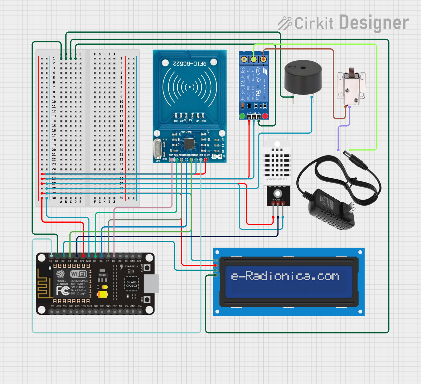
Circuit Documentation
Summary of the Circuit
This circuit appears to be designed for a smart control system, possibly for access control or environmental monitoring. It includes a microcontroller (ESP8266 NodeMCU) that interfaces with a variety of sensors and actuators. The components include a relay for controlling power to devices like a solenoid lock, a DHT22 sensor for measuring temperature and humidity, an RFID reader for access control, a buzzer for audible alerts, and an LCD screen for displaying information. The power supply provides 12V, which is used by the relay and the solenoid lock, while the other components are powered by the 3.3V output from the ESP8266 NodeMCU.
Component List
KF-301 Relay
- Description: A relay module that can be used to control high power devices.
- Pins: signal, power, ground, NC (Normally Closed), C (Common), NO (Normally Open)
DHT22
- Description: A sensor for measuring temperature and humidity.
- Pins: + (Power), Out (Signal Output), - (Ground)
LCD Screen 16x2 I2C
- Description: An alphanumeric liquid crystal display with an I2C interface.
- Pins: SCL (Serial Clock Line), SDA (Serial Data Line), VCC (Power), GND (Ground)
Buzzer
- Description: An electronic buzzer for audible alerts.
- Pins: PIN (Signal Input), GND (Ground)
ESP8266 NodeMCU
- Description: A Wi-Fi enabled microcontroller for IoT applications.
- Pins: Various GPIOs, power, and communication pins.
12V Power Supply
- Description: A power supply unit that provides 12V output.
- Pins: + (Positive), - (Negative)
RFID-RC522
- Description: An RFID reader module for reading RFID tags.
- Pins: VCC (3.3V Power), RST (Reset), GND (Ground), IRQ (Interrupt Request), MISO (Master In Slave Out), MOSI (Master Out Slave In), SCK (Serial Clock), SDA (Serial Data)
12V Solenoid Lock
- Description: An electric lock that can be controlled by applying 12V power.
- Pins: VCC (Power), GND (Ground)
Wiring Details
KF-301 Relay
- Signal: Connected to ESP8266 NodeMCU (D1)
- Power: Connected to 3.3V net (ESP8266 NodeMCU 3V3, RFID-RC522 VCC, DHT22 +, LCD VCC)
- Ground: Connected to Ground net (ESP8266 NodeMCU GND, RFID-RC522 GND, DHT22 -, Buzzer GND, LCD GND)
- NC: Not connected in this circuit
- C: Connected to 12V power supply (+)
- NO: Connected to 12V solenoid lock (VCC)
DHT22
- + (Power): Connected to 3.3V net
- Out (Signal Output): Connected to ESP8266 NodeMCU (D4)
- - (Ground): Connected to Ground net
LCD Screen 16x2 I2C
- SCL: Connected to ESP8266 NodeMCU (D1)
- SDA: Connected to ESP8266 NodeMCU (D2)
- VCC: Connected to 3.3V net
- GND: Connected to Ground net
Buzzer
- PIN (Signal Input): Connected to ESP8266 NodeMCU (D1)
- GND (Ground): Connected to Ground net
ESP8266 NodeMCU
- D0: Connected to RFID-RC522 (RST)
- D1: Connected to LCD SCL, KF-301 Relay signal, Buzzer PIN
- D2: Connected to LCD SDA
- D3: Connected to RFID-RC522 (IRQ)
- D4: Connected to DHT22 (Out)
- D5 - D8: Connected to RFID-RC522 (SCK, MISO, MOSI, SDA respectively)
- 3V3: Connected to 3.3V net
- GND: Connected to Ground net
12V Power Supply
- + (Positive): Connected to KF-301 Relay (C)
- - (Negative): Connected to 12V solenoid lock (GND)
RFID-RC522
- VCC (3.3V Power): Connected to 3.3V net
- RST (Reset): Connected to ESP8266 NodeMCU (D0)
- GND (Ground): Connected to Ground net
- IRQ (Interrupt Request): Connected to ESP8266 NodeMCU (D3)
- MISO: Connected to ESP8266 NodeMCU (D6)
- MOSI: Connected to ESP8266 NodeMCU (D7)
- SCK: Connected to ESP8266 NodeMCU (D5)
- SDA: Connected to ESP8266 NodeMCU (D8)
12V Solenoid Lock
- VCC (Power): Connected to KF-301 Relay (NO)
- GND (Ground): Connected to 12V power supply (-)
Documented Code
No code was provided for the microcontroller(s) in the circuit. Typically, the code would be documented here, including setup routines, main loop, and any interrupt service routines or function definitions. The code would also include comments explaining the purpose and functionality of each section or function.