
Arduino Nano and PWM Servo Driver-Based Battery-Powered Robotic Arm with NRF24L01 Wireless Control
View and Edit Project In Cirkit Designer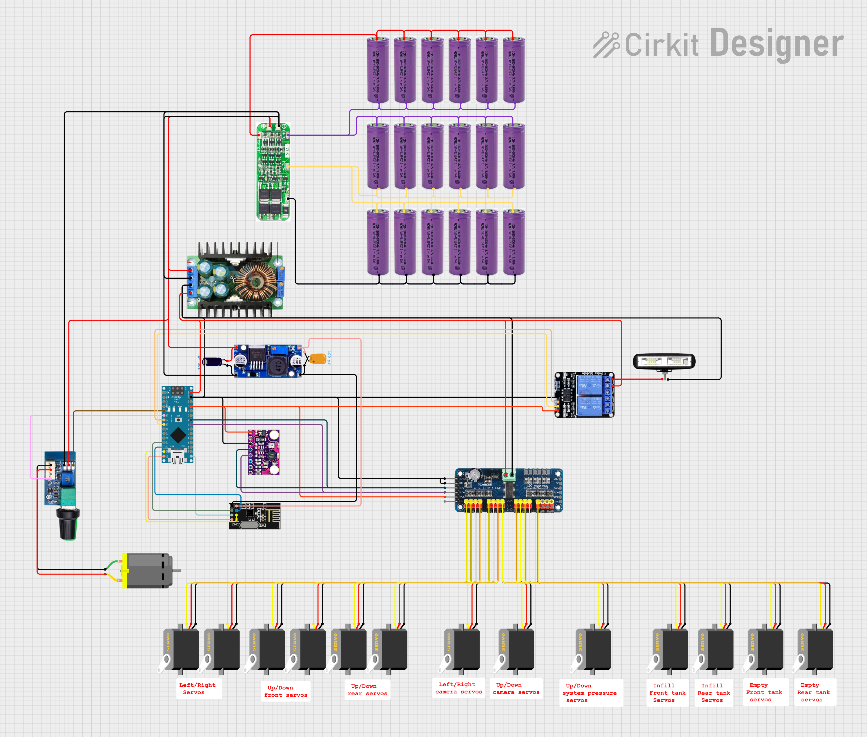
Circuit Documentation
Summary
This circuit is designed to control multiple servos, a DC motor, and a front light using an Arduino Nano microcontroller. The system includes a 16-Channel PWM Servo Driver, multiple 3.3V batteries, an NRF24L01 wireless module, and various other components. The Arduino Nano receives input from an NRF24L01 module and controls the servos and motor speed accordingly. Additionally, the circuit includes a relay to control the front light.
Component List
Servo
- Pins: gnd, vcc, pulse
- Description: A standard servo motor used for precise control of angular position.
3.3V Battery
- Pins: +, -
- Description: Provides 3.3V power supply to the circuit.
16-Channel PWM Servo Driver
- Pins: V+, VCC, SDA, SCL, OE, GND, Vin+, Vin-, PWM1 to PWM16
- Description: A driver module to control up to 16 servos using PWM signals.
NRF24L01
- Pins: IRQ (not used), MOSI, CSN, VCC (3V), GND, CE, SCK, MISO
- Description: A wireless transceiver module for communication.
Arduino Nano
- Pins: D1/TX, D0/RX, RESET, GND, D2 to D13, VIN, 5V, A0 to A7, AREF, 3V3
- Description: A small, complete, and breadboard-friendly microcontroller board.
Tantalum Capacitor
- Pins: -, +
- Description: A capacitor with a capacitance of 0.0001 Farads.
DC Motor
- Pins: pin 1, pin 2
- Description: A standard DC motor.
Front Light
- Pins: POSITIF, NEGATIF
- Description: A light used as a front light in the circuit.
Two Channel Relay 5V
- Pins: VCC, IN2, IN1, GND, NC2, C2, NO2, NC1, C1, NO1
- Description: A relay module to control high voltage devices.
MPU9250/GY-91
- Pins: 3V3, GND, SCL, SDA, VIN/5V
- Description: A 9-axis motion tracking device.
LM2596
- Pins: IN, OUT
- Description: A voltage regulator module.
3s 20A BMS
- Pins: DV/GND, 4.2V, 8.4V, 12.6V, +, -
- Description: A battery management system for 3 series cells.
DC 12V PWM Speed Controller
- Pins: S, +, -, - Output, + Output, SC/PG, PWM, Initial Speed Regulator
- Description: A speed controller for DC motors.
XL4016
- Pins: In+, In-GND, Out-GND, Out+
- Description: A DC-DC step-down converter.
Electrolytic Capacitor
- Pins: -, +
- Description: A capacitor with a capacitance of 0.0001 Farads.
Wiring Details
Servo
- gnd connected to GND of 16-Channel PWM Servo Driver
- vcc connected to V+ of 16-Channel PWM Servo Driver
- pulse connected to respective PWM pin of 16-Channel PWM Servo Driver
3.3V Battery
- + connected to - of another 3.3V Battery
- - connected to + of another 3.3V Battery
16-Channel PWM Servo Driver
- GND connected to gnd of Servo
- V+ connected to vcc of Servo
- PWM1 to PWM16 connected to pulse of respective Servo
- VCC connected to 5V of Arduino Nano, VIN/5V of MPU9250/GY-91, and VCC of Two Channel Relay 5V
- SDA connected to A4 of Arduino Nano and SDA of MPU9250/GY-91
- SCL connected to A5 of Arduino Nano and SCL of MPU9250/GY-91
- Vin- connected to OE and GND of 16-Channel PWM Servo Driver, Out-GND of XL4016, GND of Arduino Nano, GND of MPU9250/GY-91, GND of Two Channel Relay 5V, and NEGATIF of front light
- Vin+ connected to Out+ of XL4016, VIN of Arduino Nano, and C1 of Two Channel Relay 5V
NRF24L01
- MOSI connected to D11/MOSI of Arduino Nano
- CSN connected to D10 of Arduino Nano
- VCC (3V) connected to OUT of LM2596 and + of Tantalum Capacitor
- GND connected to OUT of LM2596 and - of Tantalum Capacitor
- CE connected to D9 of Arduino Nano
- SCK connected to D13/SCK of Arduino Nano
- MISO connected to D12/MISO of Arduino Nano
Arduino Nano
- 5V connected to VCC of 16-Channel PWM Servo Driver, VIN/5V of MPU9250/GY-91, and VCC of Two Channel Relay 5V
- A4 connected to SDA of 16-Channel PWM Servo Driver and SDA of MPU9250/GY-91
- A5 connected to SCL of 16-Channel PWM Servo Driver and SCL of MPU9250/GY-91
- GND connected to Vin- of 16-Channel PWM Servo Driver, Out-GND of XL4016, GND of MPU9250/GY-91, GND of Two Channel Relay 5V, and NEGATIF of front light
- VIN connected to Vin+ of 16-Channel PWM Servo Driver, Out+ of XL4016, and C1 of Two Channel Relay 5V
- D2 connected to S of DC 12V PWM Speed Controller
- D3 connected to PWM of DC 12V PWM Speed Controller
- D4 connected to IN1 of Two Channel Relay 5V
- D5 connected to IN2 of Two Channel Relay 5V
- D9 connected to CE of NRF24L01
- D10 connected to CSN of NRF24L01
- D11/MOSI connected to MOSI of NRF24L01
- D12/MISO connected to MISO of NRF24L01
- D13/SCK connected to SCK of NRF24L01
Tantalum Capacitor
- + connected to VCC (3V) of NRF24L01
- - connected to GND of NRF24L01
DC Motor
- pin 1 connected to - Output of DC 12V PWM Speed Controller
- pin 2 connected to + Output of DC 12V PWM Speed Controller
Front Light
- POSITIF connected to NO1 of Two Channel Relay 5V
- NEGATIF connected to GND of 16-Channel PWM Servo Driver
Two Channel Relay 5V
- VCC connected to 5V of Arduino Nano
- IN1 connected to D4 of Arduino Nano
- IN2 connected to D5 of Arduino Nano
- GND connected to Vin- of 16-Channel PWM Servo Driver
- NO1 connected to POSITIF of front light
- C1 connected to Vin+ of 16-Channel PWM Servo Driver
MPU9250/GY-91
- 3V3 connected to 3V3 of Arduino Nano
- GND connected to Vin- of 16-Channel PWM Servo Driver
- SCL connected to A5 of Arduino Nano and SCL of 16-Channel PWM Servo Driver
- SDA connected to **A