
Arduino Nano Controlled Dual Joystick Interface with NRF24L01 Wireless Communication
View and Edit Project In Cirkit Designer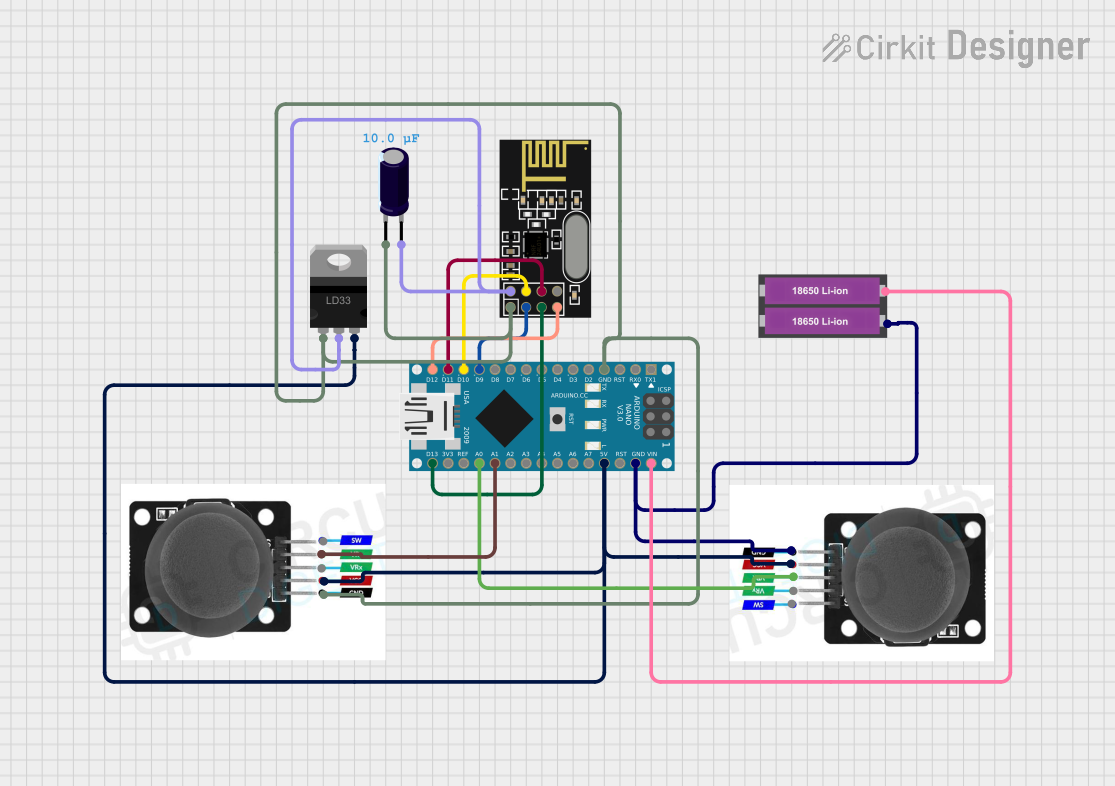
Circuit Documentation
Summary of the Circuit
This circuit is designed around an Arduino Nano microcontroller and includes a variety of components that interact with the microcontroller. The circuit features two joystick modules for user input, an NRF24L01 module for wireless communication, a power supply consisting of two 18650 Li-ion batteries, and a voltage regulator to ensure stable power delivery to the components. An electrolytic capacitor is used to smooth out any voltage spikes. The Arduino Nano is the central processing unit of the circuit, programmed to handle inputs from the joysticks and manage communication via the NRF24L01 module.
Component List
Arduino Nano
- Microcontroller board based on the ATmega328P
- Offers a variety of digital and analog I/O pins
- Can be powered via USB or an external power source
Joystick Module (2x)
- Provides analog input through two potentiometers (one for each axis)
- Includes a pushbutton switch (SW)
- Requires power (VCC) and ground (GND) connections
18650 Li-ion Battery x 2
- Provides power to the circuit
- Typically rated at 3.7V per cell
LD33 Low-Dropout Voltage Regulator
- Regulates input voltage to a stable 3.3V output
- Protects sensitive components from voltage fluctuations
NRF24L01
- 2.4GHz wireless transceiver module
- Interfaces with the microcontroller via SPI
- Powered by 3.3V and communicates wirelessly with other NRF24L01 modules
Electrolytic Capacitor
- Provides decoupling and filters out voltage spikes
- Typically polarized, with a positive (+) and negative (-) terminal
Wiring Details
Arduino Nano
- GND: Connected to the ground plane of the circuit
- D9: Connected to the CE pin of the NRF24L01 module
- D10: Connected to the CSN pin of the NRF24L01 module
- D11/MOSI: Connected to the MOSI pin of the NRF24L01 module
- D12/MISO: Connected to the MISO pin of the NRF24L01 module
- D13/SCK: Connected to the SCK pin of the NRF24L01 module
- VIN: Connected to the positive terminal of the 18650 Li-ion batteries
- 5V: Connected to the VCC pins of the joystick modules and the Vin pin of the LD33 voltage regulator
- A0: Connected to the VRX pin of one joystick module
- A1: Connected to the VRY pin of the other joystick module
Joystick Module
- SW: Not connected in the provided net list
- VRY: Connected to A1 on the Arduino Nano (for one joystick)
- VRX: Connected to A0 on the Arduino Nano (for the other joystick)
- VCC: Connected to the 5V output from the LD33 voltage regulator
- GND: Connected to the ground plane of the circuit
18650 Li-ion Battery x 2
- +: Connected to VIN on the Arduino Nano
- -: Connected to the ground plane of the circuit
LD33 Low-Dropout Voltage Regulator
- GND: Connected to the ground plane of the circuit
- Vout: Connected to the VCC (3V) pin of the NRF24L01 module and the positive terminal of the electrolytic capacitor
- Vin: Connected to the VCC pins of the joystick modules and the 5V pin on the Arduino Nano
NRF24L01
- GND: Connected to the ground plane of the circuit
- CE: Connected to D9 on the Arduino Nano
- CSN: Connected to D10 on the Arduino Nano
- MOSI: Connected to D11/MOSI on the Arduino Nano
- MISO: Connected to D12/MISO on the Arduino Nano
- SCK: Connected to D13/SCK on the Arduino Nano
- VCC (3V): Connected to the Vout of the LD33 voltage regulator and the positive terminal of the electrolytic capacitor
Electrolytic Capacitor
- -: Connected to the ground plane of the circuit
- +: Connected to the VCC (3V) pin of the NRF24L01 module
Documented Code
Arduino Nano Code (sketch.ino)
void setup() {
  // put your setup code here, to run once:

}

void loop() {
  // put your main code here, to run repeatedly:

}
The provided code is a template with empty setup() and loop() functions. The setup() function is intended for initialization code that runs once when the microcontroller is powered on or reset. The loop() function contains the main logic of the program, which runs repeatedly as long as the microcontroller is powered.
Additional Notes
- The code for the Arduino Nano is currently a placeholder and needs to be filled in with the logic for reading joystick inputs and handling wireless communication with the NRF24L01 module.
- The documentation file (documentation.txt) is empty and could be used to provide additional details about the code, such as the purpose of each function, the logic behind the code, and any libraries used.