
Arduino UNO Based Environmental Monitoring and Control System with GSM and WiFi Connectivity
View and Edit Project In Cirkit Designer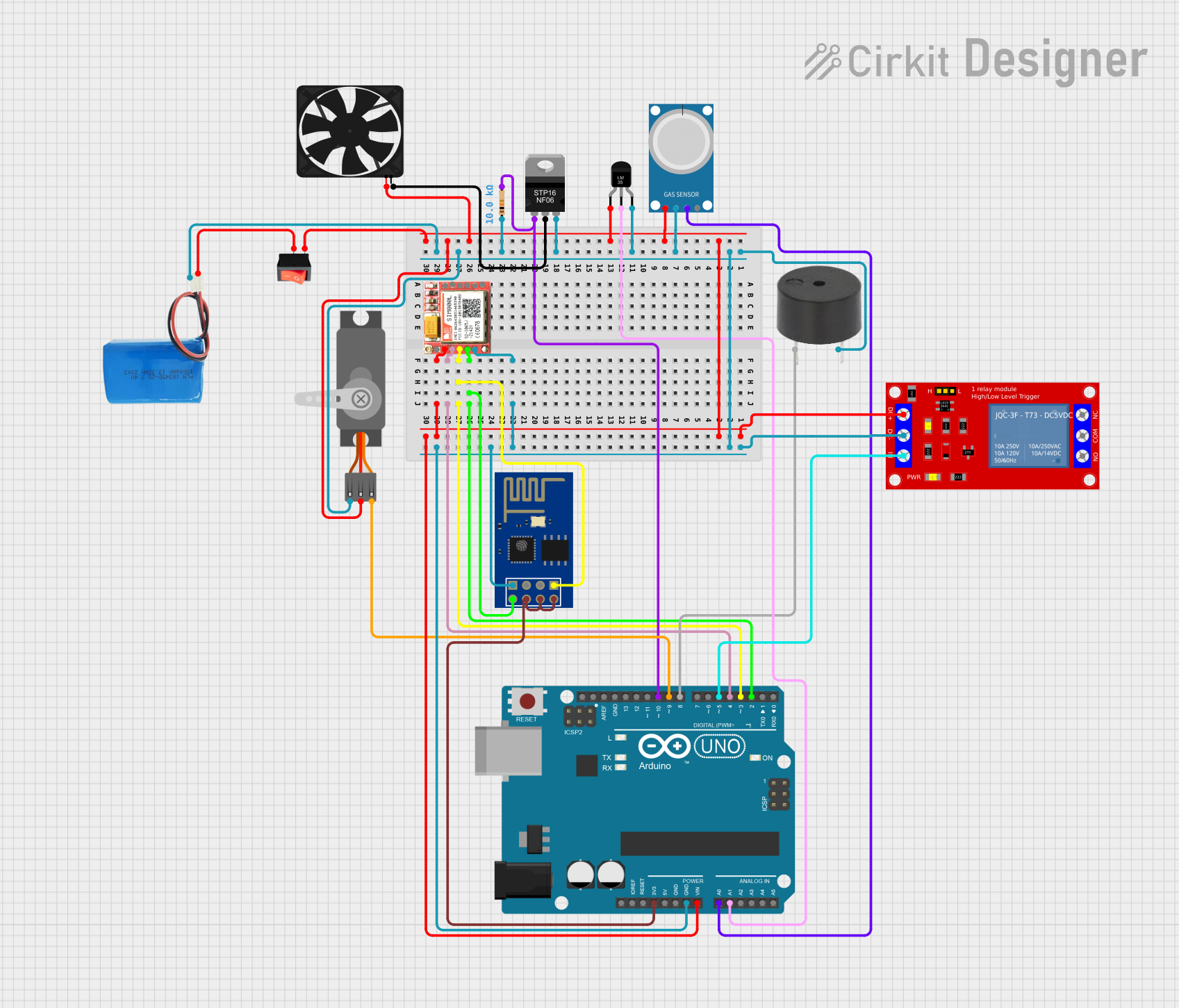
Circuit Documentation
Summary
This circuit integrates various components to perform a set of functions that likely involve sensing, actuation, communication, and control. The core of the circuit is an Arduino UNO microcontroller, which interfaces with a SIM800L GSM module, an ESP8266 WiFi module, a temperature sensor (LM35), an MQ-4 gas sensor, a power MOSFET, a servo motor, a buzzer, a fan, a relay module, and a rocker switch. The circuit is powered by a 5V battery. The Arduino UNO is programmed to control and monitor these components, enabling the circuit to interact with the environment and communicate data wirelessly.
Component List
- Arduino UNO: A microcontroller board based on the ATmega328P, with digital and analog I/O pins.
- SIM800L: A GSM/GPRS module for cellular communication.
- ESP8266 ESP-01 WiFi Module: A WiFi module for wireless network connectivity.
- STP16NF06 N-Channel Power MOSFET: A transistor used for switching electronic signals.
- Temperature Sensor (LM35): A precision integrated-circuit temperature sensor.
- MQ-4: A gas sensor for detecting natural gas and methane.
- Fan: An electric fan for cooling or ventilation.
- Servo (Wokwi Compatible): A motor with feedback control for precise positioning.
- Resistor: A passive component used to limit current or divide voltages.
- Buzzer: An audio signaling device.
- Rocker Switch: A switch to connect or disconnect the circuit.
- 5V Battery: A power source for the circuit.
- 1 Channel 5V Relay Module: An electrically operated switch that allows controlling high power devices.
Wiring Details
Arduino UNO
- GND: Connected to the common ground net.
- Vin: Connected to the VCC of SIM800L, Relay Module, MQ-4, Temperature Sensor, Fan, and Servo.
- 3.3V: Connected to VCC, CH_PD, and RST of the ESP8266 WiFi Module.
- A0: Connected to D0 of MQ-4.
- A1: Connected to Vout of Temperature Sensor (LM35).
- D2: Connected to TXD of ESP8266 WiFi Module.
- D3: Connected to RXD of ESP8266 WiFi Module.
- D4: Connected to RST of SIM800L.
- D5: Connected to IN of Relay Module.
- D8: Connected to PIN of Buzzer.
- D9: Connected to PWM of Servo.
- D10: Connected to gate of MOSFET through a Resistor.
SIM800L
- GND: Connected to the common ground net.
- VCC: Connected to the positive voltage net.
- TXD: Connected to D2 of Arduino UNO.
- RXD: Connected to D3 of Arduino UNO.
- RST: Connected to D4 of Arduino UNO.
ESP8266 ESP-01 WiFi Module
- GND: Connected to the common ground net.
- VCC, CH_PD, RST: Connected to 3.3V of Arduino UNO.
- TXD: Connected to D2 of Arduino UNO.
- RXD: Connected to D3 of Arduino UNO.
STP16NF06 N-Channel Power MOSFET
- Source: Connected to the common ground net.
- Gate: Connected to D10 of Arduino UNO through a Resistor.
- Drain: Connected to GND of Fan.
Temperature Sensor (LM35)
- GND: Connected to the common ground net.
- +Vs: Connected to the positive voltage net.
- Vout: Connected to A1 of Arduino UNO.
MQ-4 Gas Sensor
- GND: Connected to the common ground net.
- VCC: Connected to the positive voltage net.
- D0: Connected to A0 of Arduino UNO.
Fan
- 5V: Connected to the positive voltage net.
- GND: Connected to Drain of MOSFET.
Servo (Wokwi Compatible)
- GND: Connected to the common ground net.
- V+: Connected to the positive voltage net.
- PWM: Connected to D9 of Arduino UNO.
Resistor
- Pin1: Connected to the common ground net.
- Pin2: Connected to gate of MOSFET and D10 of Arduino UNO.
Buzzer
- PIN: Connected to D8 of Arduino UNO.
- GND: Connected to the common ground net.
Rocker Switch
- Input: Connected to the positive terminal of 5V Battery.
- Output: Connected to the positive voltage net.
5V Battery
- Positive: Connected to Input of Rocker Switch.
- Negative: Connected to the common ground net.
1 Channel 5V Relay Module
- VCC+: Connected to the positive voltage net.
- VCC- (GND): Connected to the common ground net.
- IN: Connected to D5 of Arduino UNO.
Documented Code
Arduino UNO Code (sketch.ino)
void setup() {
  // put your setup code here, to run once:

}

void loop() {
  // put your main code here, to run repeatedly:

}
The provided code is a template with empty setup() and loop() functions. The setup() function is intended for initialization code that runs once at the start, while the loop() function contains code that runs continuously. Specific functionality must be implemented within these functions to control and monitor the connected components.