
Arduino UNO-Based Environmental Monitoring System with SD Card Logging and LED Alerts
View and Edit Project In Cirkit Designer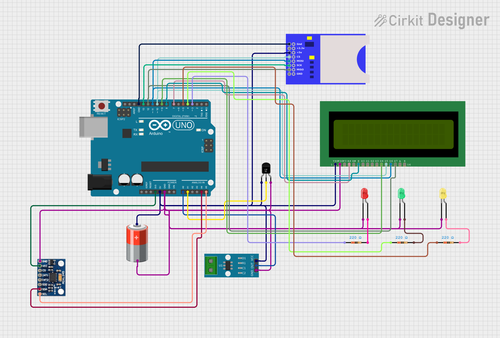
Circuit Documentation
Summary
This circuit is designed to monitor environmental conditions using various sensors and display the data on an LCD screen. It also logs the data to an SD card and provides visual alerts using LEDs. The main components include an Arduino UNO, a temperature sensor (LM35), a current sensor (ACS712), an accelerometer (ADXL345), an SD card module, an LCD display, and three LEDs (green, red, and yellow).
Component List
Arduino UNO
- Description: Microcontroller board based on the ATmega328P.
- Pins: UNUSED, IOREF, Reset, 3.3V, 5V, GND, Vin, A0, A1, A2, A3, A4, A5, SCL, SDA, AREF, D13, D12, D11, D10, D9, D8, D7, D6, D5, D4, D3, D2, D1, D0
Temperature Sensor (LM35)
- Description: Analog temperature sensor.
- Pins: +Vs, Vout, GND
SD Card Module
- Description: Module for interfacing with an SD card.
- Pins: GND, +3.3V, +5V, CS, MOSI, SCK, MISO
5V Battery
- Description: Power supply for the circuit.
- Pins: +, -
ACS712 Current Sensor
- Description: Current sensor with 5A, 20A, and 30A options.
- Pins: 1, 2, GND, OUT, VCC
ADXL345
- Description: 3-axis accelerometer.
- Pins: GND, VCC, CS, INT1, INT2, SDO, SDA, SCL
LCD 16x2 (Wokwi Compatible)
- Description: 16x2 character LCD display.
- Pins: VSS, VDD, V0, RS, RW, E, D0, D1, D2, D3, D4, D5, D6, D7, A, K
LED: Two Pin (green)
- Description: Green LED.
- Pins: cathode, anode
LED: Two Pin (red)
- Description: Red LED.
- Pins: cathode, anode
LED: Two Pin (yellow)
- Description: Yellow LED.
- Pins: cathode, anode
Resistor (220 Ohms)
- Description: Resistor with 220 Ohms resistance.
- Pins: pin1, pin2
Wiring Details
Arduino UNO
- 3.3V: Connected to VCC of ADXL345
- 5V: Connected to +5V of SD Card Module, VCC of ACS712 Current Sensor, +Vs of Temperature Sensor (LM35), and VSS of LCD 16x2
- GND: Connected to GND of ADXL345, GND of SD Card Module, GND of ACS712 Current Sensor, GND of Temperature Sensor (LM35), cathode of Green LED, cathode of Red LED, cathode of Yellow LED, and VDD of LCD 16x2
- A0: Connected to OUT of ACS712 Current Sensor
- A1: Connected to Vout of Temperature Sensor (LM35)
- A4: Connected to SDA of ADXL345
- A5: Connected to SCL of ADXL345
- D13: Connected to SCK of SD Card Module
- D12: Connected to MISO of SD Card Module and D7 of LCD 16x2
- D11: Connected to MOSI of SD Card Module and D6 of LCD 16x2
- D10: Connected to CS of SD Card Module and D5 of LCD 16x2
- D9: Connected to D4 of LCD 16x2
- D8: Connected to E of LCD 16x2
- D7: Connected to RS of LCD 16x2
- D5: Connected to pin1 of Resistor (220 Ohms)
- D4: Connected to pin1 of Resistor (220 Ohms)
- D3: Connected to pin1 of Resistor (220 Ohms)
Temperature Sensor (LM35)
- +Vs: Connected to 5V of Arduino UNO
- Vout: Connected to A1 of Arduino UNO
- GND: Connected to GND of Arduino UNO
SD Card Module
- GND: Connected to GND of Arduino UNO
- +5V: Connected to 5V of Arduino UNO
- CS: Connected to D10 of Arduino UNO
- MOSI: Connected to D11 of Arduino UNO
- SCK: Connected to D13 of Arduino UNO
- MISO: Connected to D12 of Arduino UNO
5V Battery
- +: Connected to 5V of Arduino UNO
- -: Connected to GND of Arduino UNO
ACS712 Current Sensor
- VCC: Connected to 5V of Arduino UNO
- OUT: Connected to A0 of Arduino UNO
- GND: Connected to GND of Arduino UNO
ADXL345
- VCC: Connected to 3.3V of Arduino UNO
- GND: Connected to GND of Arduino UNO
- SDA: Connected to A4 of Arduino UNO
- SCL: Connected to A5 of Arduino UNO
LCD 16x2 (Wokwi Compatible)
- VSS: Connected to 5V of Arduino UNO
- VDD: Connected to GND of Arduino UNO
- RS: Connected to D7 of Arduino UNO
- E: Connected to D8 of Arduino UNO
- D4: Connected to D9 of Arduino UNO
- D5: Connected to D10 of Arduino UNO
- D6: Connected to D11 of Arduino UNO
- D7: Connected to D12 of Arduino UNO
LED: Two Pin (green)
- cathode: Connected to GND of Arduino UNO
- anode: Connected to pin2 of Resistor (220 Ohms)
LED: Two Pin (red)
- cathode: Connected to GND of Arduino UNO
- anode: Connected to pin2 of Resistor (220 Ohms)
LED: Two Pin (yellow)
- cathode: Connected to GND of Arduino UNO
- anode: Connected to pin2 of Resistor (220 Ohms)
Resistor (220 Ohms)
- pin1: Connected to D5, D4, and D3 of Arduino UNO
- pin2: Connected to anode of Green LED, anode of Red LED, and anode of Yellow LED
Code Documentation
#include <LiquidCrystal.h>
#include <Wire.h>
#include <SPI.h>
#include <SD.h>

// Pin Definitions
#define LED_RED 3
#define LED_YELLOW 4
#define LED_GREEN 5
#define SD_CS 10
#define CURRENT_SENSOR A0
#define TEMP_SENSOR A1

// Initialize LCD (RS, EN, D4, D5, D6, D7)
LiquidCrystal lcd(7, 8, 9, 10, 11, 12);

// Variables for sensors
float current = 0.0;
float temperature = 0.0;
int16_t accX, accY, accZ;

// SD card setup
File logFile;

// ADXL345 I2C Address
#define ADXL345_ADDR 0x53

void setup() {
  // Begin serial communication
  Serial.begin(9600);

  // Initialize LCD
  lcd.begin(16, 2);
  lcd.print("Initializing...");

  // Setup LEDs
  pinMode(LED_RED, OUTPUT);
  pinMode(LED_YELLOW, OUTPUT);
  pinMode(LED_GREEN, OUTPUT);

  // Setup SD Card
  if (!SD.begin(SD_CS)) {
    lcd.clear();
    lcd.print("SD Init Failed");
    while (1);
  }
  lcd.clear();
  lcd.print("SD Init Success");

  // Initialize ADXL345
  Wire.begin();
  setupADXL345();

  delay(1000);
}

void loop() {
  // Read current from ACS712
  current = readCurrent();

  // Read temperature from LM35
  temperature = readTemperature();

  // Read vibration data from ADXL345
  readVibration();

  // Display data on LCD
  lcd.clear();
  lcd.setCursor(0, 0);
  lcd.print("I: ");
  lcd.print(current, 2);
  lcd.print("A T:");
  lcd.print(temperature, 1);
  lcd.print("C");

  lcd.setCursor(0, 1);
  lcd.print("X:");