Cirkit Designer
Your all-in-one circuit design IDE
Home /
Project Documentation
Arduino Mega 2560-Controlled Fire Detection and Response Robot
Circuit Documentation
Summary
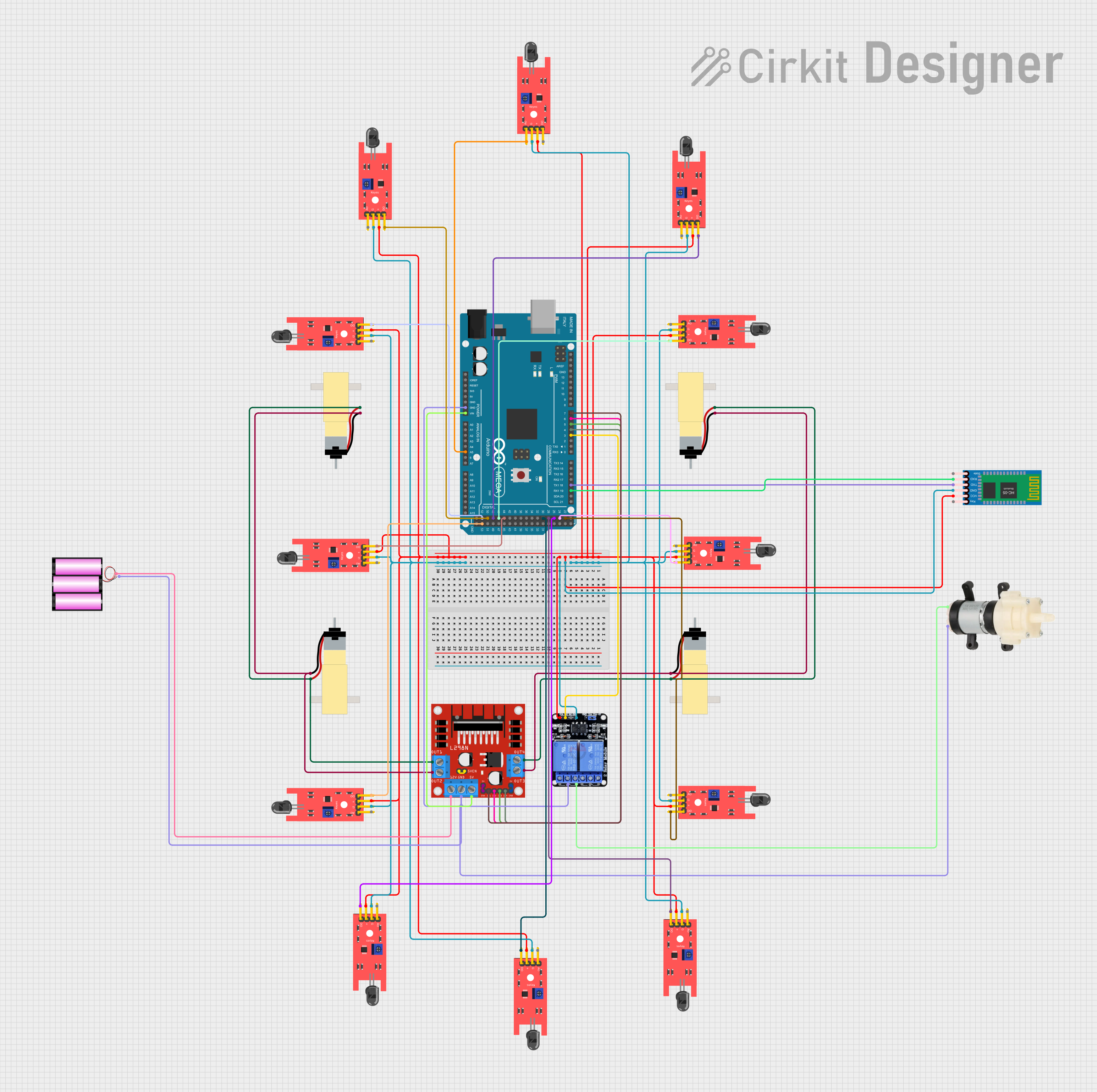
This circuit is designed to interface various sensors, actuators, and modules with an Arduino Mega 2560 microcontroller. It includes flame sensors for detection, a Bluetooth module for wireless communication, a motor driver to control gearmotors, a diaphragm water pump, and a relay module for switching high-power devices. The circuit is powered by a 12V battery, and the Arduino Mega 2560 is the central processing unit that manages inputs from the sensors and controls the actuators based on the programmed logic.
Component List
Microcontroller
- Arduino Mega 2560: A microcontroller board based on the ATmega2560 with numerous digital and analog I/O pins.
Motor Driver
- L298N DC Motor Driver: A module capable of driving two DC motors or one stepper motor with logic voltage levels compatible with the Arduino.
Motors
- Hobby Gearmotor with 48:1 Gearbox: A DC motor with a gearbox for increased torque, used for driving mechanical parts.
Pump
- Mini Diaphragm Water Pump: A small pump used for moving water or other fluids.
Communication Module
- HC-05 Bluetooth Module: A wireless communication module that allows for Bluetooth connectivity.
Sensors
- KY-026 Flame Sensor: A sensor that detects fire or flame presence with both analog and digital outputs.
Relay Module
- Two Channel Relay 5v: A module with two relays that can switch high voltage/high current loads.
Power Source
- Battery 12V: A 12-volt battery that provides power to the circuit.
Wiring Details
Arduino Mega 2560
- Digital Pins:
- D19/RX1: Connected to TXD of HC-05 Bluetooth Module
- D18/TX1: Connected to RXD of HC-05 Bluetooth Module
- D3 PWM: Connected to IN2 of Two Channel Relay 5v
- D4 PWM: Connected to IN4 of L298N DC Motor Driver
- D5 PWM: Connected to IN3 of L298N DC Motor Driver
- D6 PWM: Connected to IN2 of L298N DC Motor Driver
- D7 PWM: Connected to IN1 of L298N DC Motor Driver
- D22 to D53: Connected to D0 of various KY-026 Flame Sensors
- Analog Pins:
- A5: Connected to A0 of a KY-026 Flame Sensor
- Power Pins:
- VIN: Connected to 5V of L298N DC Motor Driver
- GND: Connected to GND of various components
L298N DC Motor Driver
- Motor Outputs:
- OUT1, OUT2: Connected to two pins of a pair of Hobby Gearmotors
- OUT3, OUT4: Connected to two pins of another pair of Hobby Gearmotors
- Power Inputs:
- 12V: Connected to + of the 12V battery
- 5V: Connected to VIN of Arduino Mega 2560
- GND: Connected to GND of Arduino Mega 2560
- Control Inputs:
- IN1 to IN4: Controlled by D4 PWM to D7 PWM of Arduino Mega 2560
- Enable Pins:
- ENA, ENB: Connected to +5V-J1 and +5V-J2 respectively
Hobby Gearmotor with 48:1 Gearbox
- Four motors are used, each connected to OUT1, OUT2, OUT3, and OUT4 of the L298N DC Motor Driver.
Mini Diaphragm Water Pump
- Positive (+): Connected to NO2 of Two Channel Relay 5v
- Negative (-): Connected to - of the 12V battery
HC-05 Bluetooth Module
- VCC: Connected to 5V power rail
- GND: Connected to GND power rail
- TXD: Connected to D19/RX1 of Arduino Mega 2560
- RXD: Connected to D18/TX1 of Arduino Mega 2560
KY-026 Flame Sensor
- Multiple sensors are used, each with VCC connected to 5V power rail and GND to GND power rail.
- A0 of one sensor is connected to A5 of Arduino Mega 2560.
- D0 of each sensor is connected to individual digital pins D22 to D53 of Arduino Mega 2560.
Two Channel Relay 5v
- VCC: Connected to 5V power rail
- GND: Connected to GND power rail
- IN2: Controlled by D3 PWM of Arduino Mega 2560
- NO2: Connected to Positive (+) of Mini Diaphragm Water Pump
Battery 12V
- +: Connected to 12V of L298N DC Motor Driver
- -: Connected to GND power rail
Documented Code
Arduino Mega 2560 - sketch.ino
void setup() {
  // put your setup code here, to run once:

}

void loop() {
  // put your main code here, to run repeatedly:

}
Arduino Mega 2560 - documentation.txt
(No additional documentation provided for the code)
This concludes the documentation for the circuit. The code provided is a template and needs to be filled in with the logic to control the circuit based on the requirements.