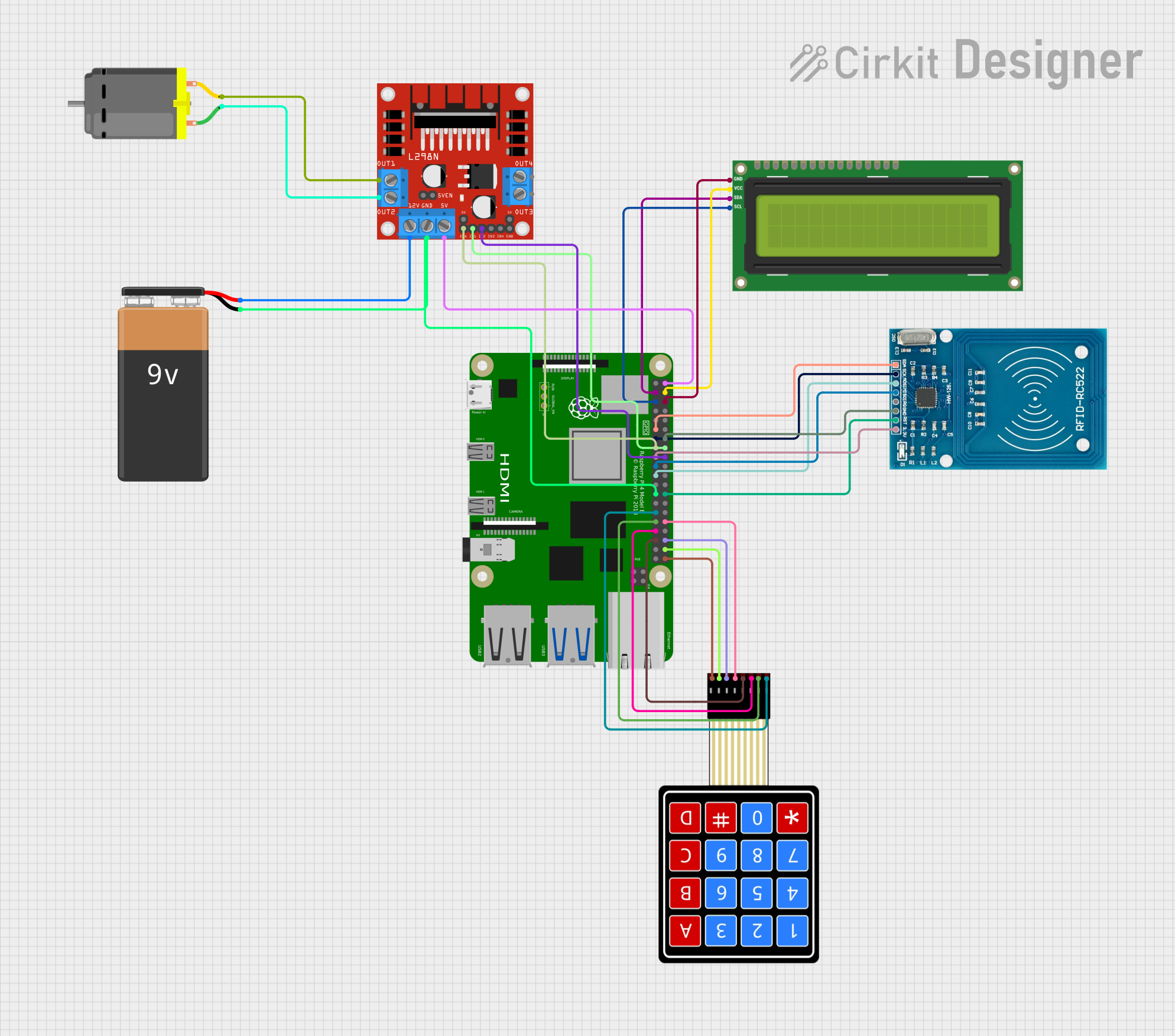
Raspberry Pi 4B Controlled RFID and Keypad Security System with I2C LCD Feedback and Motorized Lock Mechanism

Circuit Documentation
Summary
This circuit integrates a Raspberry Pi 4B with various peripherals including an I2C LCD 16x2 screen, an RFID-RC522 module, a 4x4 membrane matrix keypad, an L298N DC motor driver, and a DC motor. The circuit is powered by a 9V battery. The Raspberry Pi 4B serves as the central processing unit, interfacing with the I2C LCD screen for display, the RFID module for scanning RFID tags, the keypad for user input, and the motor driver to control the DC motor. The circuit is designed for applications that require user interaction, display feedback, RFID reading capabilities, and motor control.
Component List
Raspberry Pi 4B
- A microcomputer with multiple GPIO pins used for interfacing with other components in the circuit.
I2C LCD 16x2 Screen
- A 16x2 character LCD display that uses the I2C communication protocol for displaying information.
RFID-RC522
- An RFID reader/writer module that operates at 13.56 MHz and uses SPI for communication with the Raspberry Pi.
4X4 Membrane Matrix Keypad
- A 16-button keypad that provides user input capabilities to the circuit.
L298N DC Motor Driver
- A motor driver module capable of driving a small DC motor, controlled via GPIO pins from the Raspberry Pi.
DC Motor
- A small electric motor driven by the L298N motor driver.
9V Battery
- A power source for the motor driver and the motor.
Wiring Details
Raspberry Pi 4B
- 5V: Powers the I2C LCD screen and the L298N motor driver.
- GPIO2 (SDA): Connected to the SDA pin of the I2C LCD screen for data communication.
- GPIO3 (SCL): Connected to the SCL pin of the I2C LCD screen for clock signal.
- GND: Common ground for the I2C LCD screen, RFID-RC522, and L298N motor driver.
- GPIO4 - GPIO27: Various GPIO pins used for interfacing with the RFID-RC522 and the L298N motor driver.
- 3V3: Powers the RFID-RC522 module.
I2C LCD 16x2 Screen
- SDA: Connected to GPIO2 (SDA) on the Raspberry Pi for data communication.
- SCL: Connected to GPIO3 (SCL) on the Raspberry Pi for clock signal.
- VCC (5V): Powered by the 5V pin on the Raspberry Pi.
- GND: Connected to the common ground on the Raspberry Pi.
RFID-RC522
- SDA: Connected to GPIO17 on the Raspberry Pi.
- SCK, MISO, MOSI: Connected to GPIO27, GPIO10, and GPIO9 respectively on the Raspberry Pi for SPI communication.
- RST: Connected to GPIO7 on the Raspberry Pi for reset control.
- VCC (3.3V): Powered by the 3V3 pin on the Raspberry Pi.
- GND: Connected to the common ground on the Raspberry Pi.
4X4 Membrane Matrix Keypad
- R1 - R4: Connected to GPIO5, GPIO6, GPIO13, and GPIO19 respectively on the Raspberry Pi.
- C1 - C4: Connected to GPIO12, GPIO16, GPIO20, and GPIO21 respectively on the Raspberry Pi.
L298N DC Motor Driver
- ENA: Connected to GPIO22 on the Raspberry Pi for enabling the motor driver.
- IN1, IN2: Connected to GPIO23 and GPIO24 on the Raspberry Pi for motor direction control.
- 5V: Powered by the 5V pin on the Raspberry Pi.
- GND: Connected to the common ground on the Raspberry Pi.
- 12V: Powered by the "+" pin of the 9V battery.
- OUT1, OUT2: Connected to the two pins of the DC motor to drive it.
DC Motor
- Pin 1, Pin 2: Connected to OUT2 and OUT1 on the L298N motor driver to receive power and control signals.
9V Battery
- +: Powers the L298N motor driver.
- -: Connected to the common ground in the circuit.
Documented Code
No code was provided for the microcontrollers in the circuit. Therefore, this section is not applicable for the current documentation. If code becomes available, it should be documented here with descriptions of its functionality and how it interfaces with the hardware components.