
Circuit Documentation
Summary
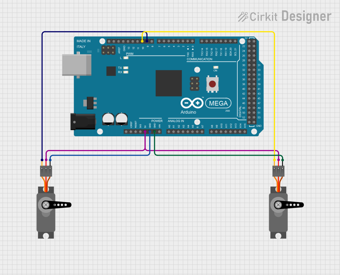
This circuit consists of an Arduino Mega 2560 microcontroller and two servo motors. The Arduino Mega 2560 is used to control the servo motors by providing PWM signals. The servos are powered by the 5V output from the Arduino and share a common ground.
Component List
Arduino Mega 2560
- Description: A microcontroller board based on the ATmega2560.
- Pins: IOREF, RESET, 3V3, 5V, GND, VIN, A0-A15, D21/SCL, D20/SDA, D19/RX1, D18/TX1, D17 PWM/RX2, D16 PWM/TX2, D15/RX3, D14/TX3, D0 RX0, D1 TX0, D2 PWM, D3 PWM, D4 PWM, D5 PWM, D6 PWM, D7 PWM, D8 PWM, D9 PWM, D10 PWM, D11 PWM, D12 PWM, D13 PWM, AREF, SDA, SCL, D52, D50, D48, D46, D44, D42, D40, D38, D36, D34, D32, D30, D28, D26, D24, D22, D53, D51, D49, D47, D45, D43, D41, D39, D37, D35, D33, D31, D29, D27, D25, D23, 6swdw
Servo Motor 1
- Description: A standard servo motor.
- Pins: GND, VCC, PWM
Servo Motor 2
- Description: A standard servo motor.
- Pins: GND, VCC, PWM
Wiring Details
Arduino Mega 2560
- 5V: Connected to VCC of Servo Motor 1 and Servo Motor 2
- GND: Connected to GND of Servo Motor 1 and Servo Motor 2
- D9 PWM: Connected to PWM of Servo Motor 1
- D10 PWM: Connected to PWM of Servo Motor 2
Servo Motor 1
- VCC: Connected to 5V of Arduino Mega 2560
- GND: Connected to GND of Arduino Mega 2560
- PWM: Connected to D9 PWM of Arduino Mega 2560
Servo Motor 2
- VCC: Connected to 5V of Arduino Mega 2560
- GND: Connected to GND of Arduino Mega 2560
- PWM: Connected to D10 PWM of Arduino Mega 2560
Code Documentation
Arduino Mega 2560 Code
void setup() {
  // put your setup code here, to run once:

}

void loop() {
  // put your main code here, to run repeatedly:

}
This code is a basic template for the Arduino Mega 2560. The setup() function is where you initialize your components and settings, and the loop() function is where you place the main code that runs repeatedly.