
Arduino UNO-Based Weather Monitoring and GPS Tracking System with LoRa Communication
View and Edit Project In Cirkit Designer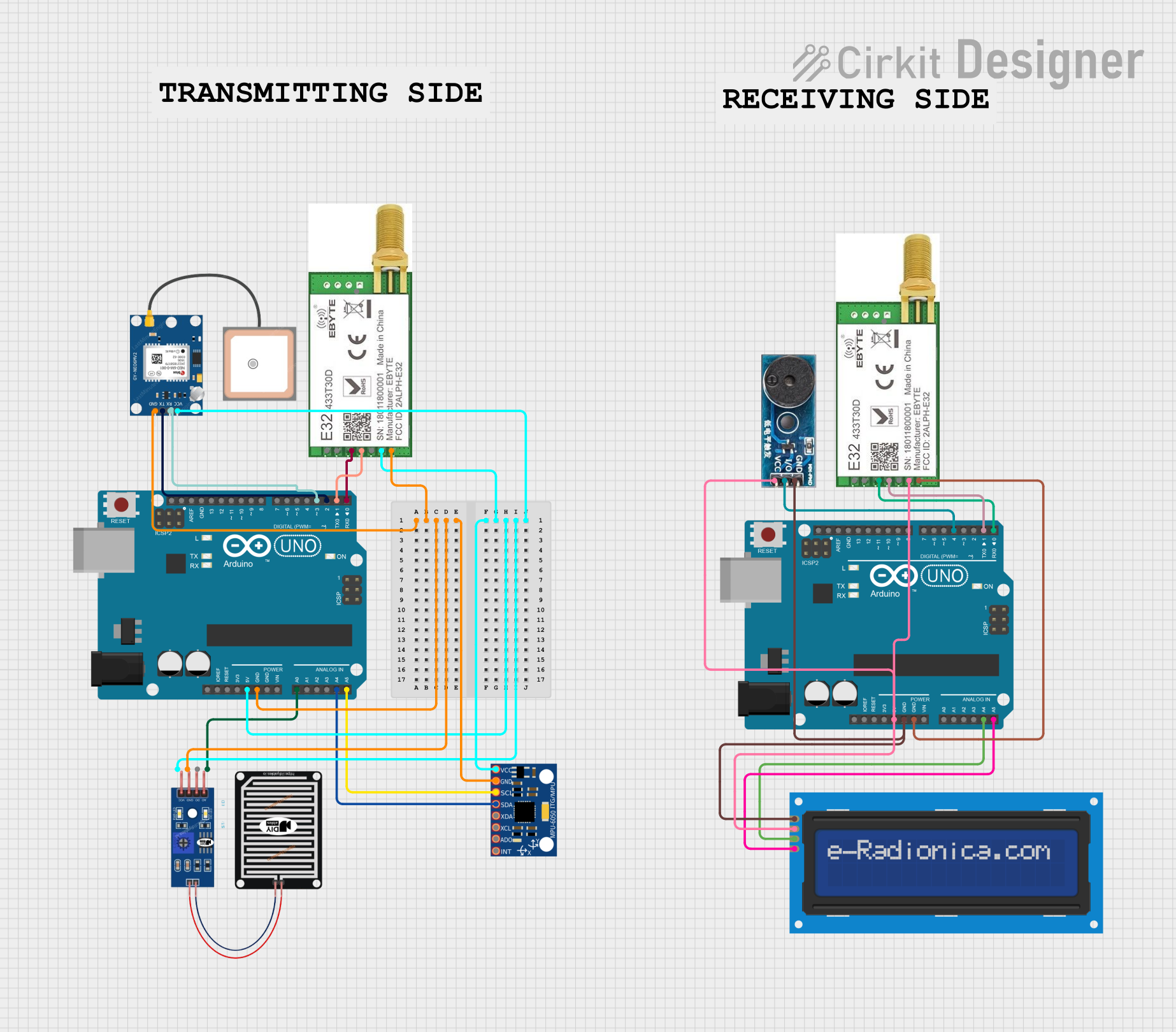
Circuit Documentation
Summary
The circuit in question is designed around two Arduino UNO microcontrollers, which serve as the central processing units. The circuit includes a variety of sensors and modules to perform different functions. These include an MPU-6050 for motion tracking, a GPS NEO 6M module for location tracking, a rain sensor for detecting rainfall, and a LoRa module for long-range communication. Additionally, the circuit features a buzzer module for audio feedback and an LCD screen with I2C interface for displaying information. The components are powered through the 5V and GND pins of the Arduino UNOs, and communication between the sensors, modules, and the Arduino is established via digital and analog I/O pins, as well as I2C communication lines.
Component List
Arduino UNO
- Microcontroller board based on the ATmega328P
- Features digital I/O pins, analog input pins, and dedicated pins for power and ground
MPU-6050
- Motion tracking device with a 3-axis gyroscope and a 3-axis accelerometer
- Communicates with the Arduino via the I2C protocol
Rain Sensor
- Detects rain by measuring the resistance between two conductive tracks
- Outputs an analog signal to the Arduino
GPS NEO 6M
- GPS module that provides location data
- Communicates with the Arduino via serial communication (TX/RX)
LoRa Module
- Long-range communication module using LoRa technology
- Capable of transmitting and receiving data over long distances
Buzzer Module
- Produces an audible tone when activated
- Controlled by a digital I/O pin on the Arduino
LCD Screen 16x2 I2C
- Alphanumeric liquid crystal display with 16 characters by 2 lines
- Uses the I2C protocol for communication with the Arduino
Wiring Details
Arduino UNO
- 5V and GND pins are used to power the connected components
- Analog and digital I/O pins are used for interfacing with sensors and modules
MPU-6050
- VCC and GND pins are connected to the 5V and GND of the Arduino for power
- SDA and SCL pins are connected to the A4 and A5 pins (I2C) of the Arduino
Rain Sensor
- VCC and GRD pins are connected to the 5V and GND of the Arduino for power
- AO pin is connected to the A0 analog input pin of the Arduino
GPS NEO 6M
- VCC and GND pins are connected to the 5V and GND of the Arduino for power
- RX and TX pins are connected to the D3 and D2 digital I/O pins of the Arduino
LoRa Module
- VCC and GND pins are connected to the 5V and GND of the Arduino for power
- TXD and RXD pins are connected to the D1 and D0 digital I/O pins of the Arduino
Buzzer Module
- Vcc and GND pins are connected to the 5V and GND of the Arduino for power
- I/O pin is connected to the D4 digital I/O pin of the Arduino
LCD Screen 16x2 I2C
- VCC and GND pins are connected to the 5V and GND of the Arduino for power
- SDA and SCL pins are connected to the A4 and A5 pins (I2C) of the Arduino
Documented Code
Arduino UNO (Primary Microcontroller)
sketch.ino
void setup() {
  // put your setup code here, to run once:

}

void loop() {
  // put your main code here, to run repeatedly:

}
Arduino UNO (Secondary Microcontroller)
sketch.ino
void setup() {
  // put your setup code here, to run once:

}

void loop() {
  // put your main code here, to run repeatedly:

}
Note: The provided code snippets are templates and do not contain any functional code. They are placeholders for where the user would add their own setup and loop code.