
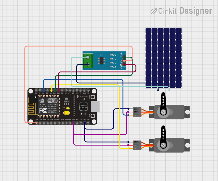
Circuit Documentation
Summary
The circuit in question is designed to interface an ESP8266 NodeMCU microcontroller with two servo motors and a current sensor. The current sensor is connected to a solar panel for monitoring its output current. The ESP8266 NodeMCU controls the servo motors via PWM signals and reads the current sensor output through an analog input. The servos and the current sensor are powered by the 3.3V supply from the ESP8266 NodeMCU, and all components share a common ground.
Component List
ESP8266 NodeMCU
- Description: A Wi-Fi capable microcontroller module based on the ESP8266 chip.
- Pins: D0, D1, D2, D3, D4, 3V3, GND, D5, D6, D7, D8, RX, TX, A0, RSV, SD3, SD2, SD1, CMD, SD0, CLK, EN, RST, VIN
Servo (x2)
- Description: An electromechanical device that can rotate to a specified position using a PWM control signal.
- Pins: GND, VCC, PWM
Solar Panel
- Description: A photovoltaic panel that converts sunlight into electrical energy.
- Pins: +, -
Current Sensor 5A
- Description: A sensor used to measure up to 5A of current flowing through it.
- Pins: 1, 2, GND, OUT, VCC
Wiring Details
ESP8266 NodeMCU
- D2 connected to Servo (PWM)
- D4 connected to Servo (PWM)
- 3V3 connected to Current Sensor 5A (VCC), Servo (VCC), Servo (VCC)
- GND connected to Current Sensor 5A (GND), Servo (GND), Servo (GND)
- A0 connected to Current Sensor 5A (OUT)
Servo
- PWM connected to ESP8266 NodeMCU (D2 or D4)
- VCC connected to ESP8266 NodeMCU (3V3)
- GND connected to ESP8266 NodeMCU (GND)
Solar Panel
- + connected to Current Sensor 5A (2)
- - connected to Current Sensor 5A (1)
Current Sensor 5A
- VCC connected to ESP8266 NodeMCU (3V3)
- GND connected to ESP8266 NodeMCU (GND)
- OUT connected to ESP8266 NodeMCU (A0)
- 2 connected to Solar Panel (+)
- 1 connected to Solar Panel (-)
Code Documentation
No code has been provided for the microcontroller. The expected code should initialize the Wi-Fi capabilities of the ESP8266 NodeMCU, configure the PWM outputs for the servo motors, and set up the ADC for reading the current sensor output. The code should also include routines for controlling the servo positions and reading the current sensor data, possibly sending this data to a remote server or displaying it locally.