
Arduino UNO-Based Water Level and Distance Monitoring System with RGB Feedback
View and Edit Project In Cirkit Designer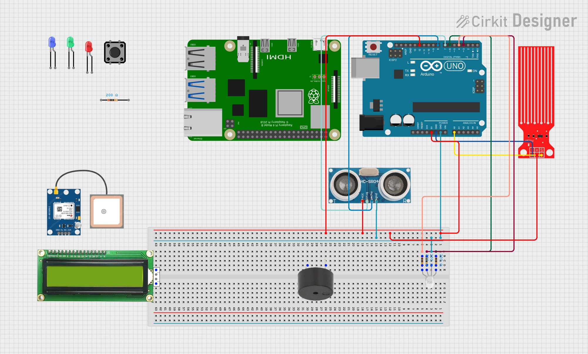
Circuit Documentation
Summary
This circuit integrates a variety of components including a microcontroller, sensors, an RGB LED, individual LEDs, a buzzer, a GPS module, resistors, and a tactile switch button. The microcontroller used is an Arduino UNO, which interfaces with a water level sensor and an ultrasonic sensor for sensing purposes. The RGB LED and individual red, green, and blue LEDs are used for visual indications, and their current is limited by resistors. The buzzer provides audible alerts, and the GPS NEO 6M module allows for location tracking. The tactile switch button serves as a user input device. The circuit is powered by the Arduino UNO's 5V output, and common ground connections are established for the components requiring them.
Component List
Microcontroller
- Arduino UNO: A microcontroller board based on the ATmega328P, featuring digital and analog I/O pins.
Sensors
- Water Level Sensor: A device that detects the level of water in a container or environment.
- Ultrasonic Sensor: A sensor that measures distance by emitting ultrasonic waves and timing their reflection.
Indicators
- RGB LED (Wokwi compatible): A four-pin LED with red, green, and blue elements that can be combined to create different colors.
- LED: Two Pin (red): A simple red LED for indication purposes.
- LED: Two Pin (green): A simple green LED for indication purposes.
- LED: Two Pin (blue): A simple blue LED for indication purposes.
Output Devices
- Buzzer: An electronic buzzer for audible alerts.
Communication Modules
- GPS NEO 6M: A GPS module for obtaining geographical location data.
Passive Components
- Resistor: A component that provides resistance to the flow of electric current, used here to limit the current through LEDs.
User Input
- Tactile Switch Buttons - 12mm Square: A simple push-button switch for user input.
Display
- MKE-M07 LCD1602 I2C: An alphanumeric liquid crystal display module for showing text and numbers.
Wiring Details
Arduino UNO
- 5V: Powers the Water Level Sensor, Ultrasonic Sensor, and other 5V components.
- GND: Common ground for Water Level Sensor, Ultrasonic Sensor, and RGB LED.
- A0: Connected to the signal pin of the Water Level Sensor.
- D12: Connected to the 5V power net (possibly for power distribution).
- D8: Connected to the Echo pin of the Ultrasonic Sensor.
- D7: Connected to the Trigger pin of the Ultrasonic Sensor.
- D6, D4, D3: Connected to the RGB LED through resistors.
RGB LED (Wokwi compatible)
- R: Connected to Arduino UNO D6 through a 200 Ohm resistor.
- G: Connected to Arduino UNO D3 through a 200 Ohm resistor.
- B: Connected to Arduino UNO D4 through a 200 Ohm resistor.
- COM: Connected to GND.
Water Level Sensor
- SIG: Connected to Arduino UNO A0.
- VCC: Powered by Arduino UNO 5V.
- GND: Connected to common ground.
Ultrasonic Sensor
- +VCC: Powered by Arduino UNO 5V.
- Trigger: Connected to Arduino UNO D7.
- Echo: Connected to Arduino UNO D8.
- GND: Connected to common ground.
Resistor
- Four resistors are used, each with a resistance of 200 Ohms, to limit the current through the RGB LED.
Documented Code
Arduino UNO Code (sketch.ino)
void setup() {
  // put your setup code here, to run once:

}

void loop() {
  // put your main code here, to run repeatedly:

}
Note: The provided code is a template and does not contain any functional code. It needs to be populated with the logic to control the sensors, LEDs, and other components based on the requirements of the circuit's application.