
Wireless Audio Communication System with Arduino and NRF24L01
View and Edit Project In Cirkit Designer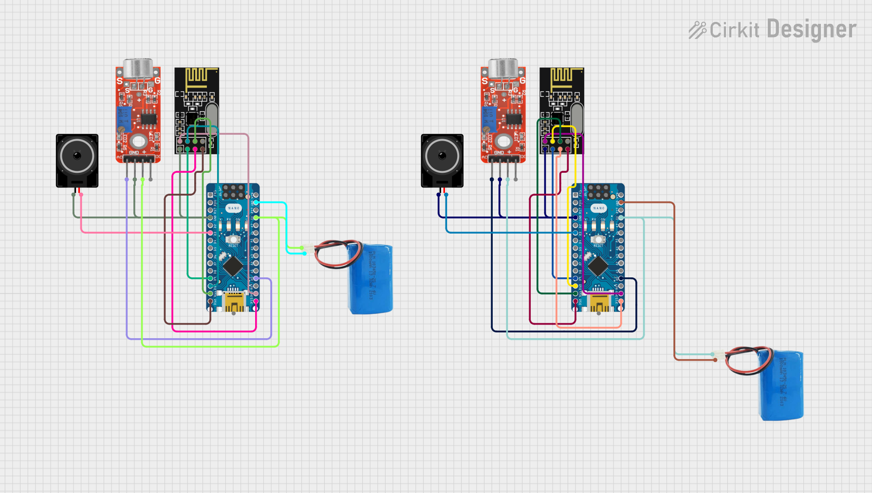
Circuit Documentation
Summary
This circuit consists of two main subsystems, each built around an Arduino Nano microcontroller. The subsystems are designed to communicate with each other wirelessly using NRF24L01 transceiver modules. Each subsystem also includes a KY-037 Microphone module for audio input and a Loudspeaker for audio output. The microphones capture audio signals, which are then transmitted wirelessly between the two Arduinos, and the received signals are played out through the loudspeakers. The circuit is powered by two separate 5V batteries.
Component List
Microcontrollers
- Arduino Nano: A compact microcontroller board based on the ATmega328P, featuring digital and analog I/O pins.
Communication Modules
- NRF24L01: A 2.4GHz wireless transceiver module that enables communication between microcontrollers.
Sensors
- KY-037 Microphone: A sound detection sensor module that provides both digital and analog outputs.
Output Devices
- Loudspeaker: An electroacoustic transducer that converts an electrical audio signal into a corresponding sound.
Power Sources
- 5V Battery: Provides the necessary power to the circuit components.
Wiring Details
Arduino Nano
- Digital I/O Pins: Used for interfacing with the NRF24L01 module and the Loudspeaker.
- Analog Input Pins: Used to read the analog signal from the KY-037 Microphone module.
- Power Pins (5V, GND, 3V3): Provide power to the Arduino itself, the NRF24L01 module, and the KY-037 Microphone module.
NRF24L01
- MOSI, MISO, SCK: Connected to the corresponding SPI pins on the Arduino Nano for data communication.
- CSN, CE: Connected to digital I/O pins on the Arduino Nano for module control.
- VCC, GND: Connected to the power supply pins on the Arduino Nano.
KY-037 Microphone
- Analog Output: Connected to an analog input pin on the Arduino Nano to read the audio signal.
- VCC, Ground: Connected to the power supply pins on the Arduino Nano.
Loudspeaker
- Pin1 (GND): Connected to the ground pin on the Arduino Nano.
- Pin2: Connected to a digital I/O pin on the Arduino Nano for audio signal output.
5V Battery
- Positive: Connected to the 5V power pin on the Arduino Nano.
- Negative: Connected to the ground pin on the Arduino Nano.
Documented Code
Arduino Nano Code (for both microcontrollers)
#include <SPI.h>
#include <RF24.h>

RF24 radio(9, 10); // CE, CSN pins

const int micPin = A0; // Microphone pin
const int speakerPin = 3; // Speaker pin

void setup() {
  pinMode(speakerPin, OUTPUT);
  Serial.begin(9600);
  radio.begin();
  radio.openWritingPipe(0xF0F0F0F0E1LL);
  radio.openReadingPipe(1, 0xF0F0F0F0E2LL);
  radio.setChannel(1);
  radio.setPALevel(RF24_PA_HIGH);
  radio.startListening();
}

void loop() {
  // Send data if listening
  if (radio.available()) {
    // Receiving data
    byte receivedValue;
    radio.read(&receivedValue, sizeof(receivedValue));
    // Output sound to speaker
    tone(speakerPin, receivedValue); // Using received value as frequency
  } else {
    // Read microphone input
    int micValue = analogRead(micPin);
    // Send microphone value
    radio.write(&micValue, sizeof(micValue));
    delay(100); // Adjust as necessary
  }
}
This code is designed to run on both Arduino Nano microcontrollers in the circuit. It initializes the RF24 library for wireless communication, sets up the microphone and speaker pins, and enters a loop where it either sends microphone data or receives data to play on the speaker. The tone() function is used to generate a sound on the speaker based on the received value.