
ESP32-Controlled Environmental Monitoring and Fan Regulation System
View and Edit Project In Cirkit Designer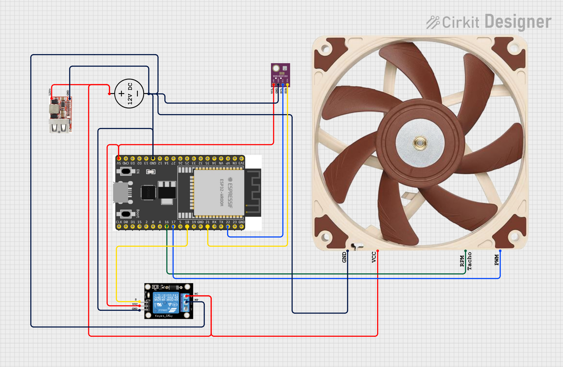
Circuit Documentation
Summary
This circuit integrates a variety of components including a BME/BMP280 sensor, an ESP 32 Wroom Dev Kit microcontroller, a DC power source, a KY-019 Relay module, a USB regulator, and a 12v PWM Fan. The circuit is designed to measure environmental data using the BME/BMP280 sensor, control a relay module, and manage a PWM fan, all orchestrated by the ESP 32 microcontroller. The USB regulator is used to step down the voltage for certain components, and the DC power source provides the necessary power for the circuit.
Component List
BME/BMP280
- Description: A precision sensor that can measure temperature, humidity, and pressure.
- Pins: GND, SCL, SDA, VIN
ESP 32 Wroom Dev Kit
- Description: A powerful microcontroller with Wi-Fi and Bluetooth capabilities.
- Pins: Multiple GPIOs, 3V3, EN, VP, VN, GND, TXD, RXD, SD1, SD0, CLK, V5
DC Power Source
- Description: Provides the electrical power for the circuit.
- Pins: Ground, Positive
KY-019 Relay module 1 channel
- Description: A relay module that can control high power devices.
- Pins: S, 5V, GND, NC, COM, NO
USB Regulator
- Description: Regulates the USB power supply to 5V output.
- Pins: VIN+, VIN-, 5V_USB_VO
12v PWM Fan (120mm)
- Description: A 12V fan with PWM control for speed regulation.
- Pins: GND, +12V, TACH, PWM
Comments
- Description: Placeholder for additional notes or comments in the circuit.
Wiring Details
BME/BMP280
- GND connected to common ground net.
- SCL connected to ESP 32 Wroom Dev Kit GPIO 22.
- SDA connected to ESP 32 Wroom Dev Kit GPIO 21.
- VIN connected to 5V from the ESP 32 Wroom Dev Kit.
ESP 32 Wroom Dev Kit
- GND connected to common ground net.
- GPIO 22 connected to BME/BMP280 SCL.
- GPIO 21 connected to BME/BMP280 SDA.
- V5 connected to KY-019 Relay module 5V and BME/BMP280 VIN.
- GPIO 18 connected to KY-019 Relay module S.
- GPIO 17 connected to 12v PWM Fan PWM.
- GPIO 16 connected to 12v PWM Fan TACH.
DC Power Source
- Ground connected to common ground net.
- Positive connected to USB Regulator VIN+ and 12v PWM Fan +12V.
KY-019 Relay module 1 channel
- S connected to ESP 32 Wroom Dev Kit GPIO 18.
- 5V connected to ESP 32 Wroom Dev Kit V5.
- GND connected to common ground net.
- COM connected to common ground net.
- NC connected to USB Regulator VIN+.
USB Regulator
- VIN- connected to common ground net.
- VIN+ connected to DC Power Source Positive and 12v PWM Fan +12V.
12v PWM Fan (120mm)
- GND connected to common ground net.
- +12V connected to USB Regulator VIN+ and DC Power Source Positive.
- TACH connected to ESP 32 Wroom Dev Kit GPIO 16.
- PWM connected to ESP 32 Wroom Dev Kit GPIO 17.
Documented Code
No code has been provided for the microcontrollers in the circuit. When code is available, it should be documented here with explanations for each function and routine, including setup and loop functions, interrupt service routines, and any custom functions used to control the hardware components listed above.