
Arduino UNO Light Detection System with 16x2 I2C LCD Display
View and Edit Project In Cirkit Designer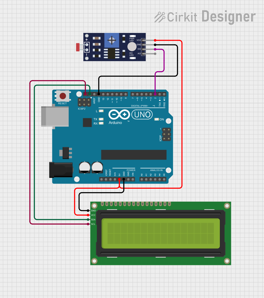
Circuit Documentation
Summary
This circuit consists of an Arduino UNO microcontroller, a 16x2 I2C LCD display, and a photoresistor (LDR) sensor. The Arduino UNO reads the light intensity from the LDR sensor and displays the status ("Light" or "Dark") on the LCD screen.
Component List
Arduino UNO
- Description: A microcontroller board based on the ATmega328P.
- Pins: UNUSED, IOREF, Reset, 3.3V, 5V, GND, Vin, A0, A1, A2, A3, A4, A5, SCL, SDA, AREF, D13, D12, D11, D10, D9, D8, D7, D6, D5, D4, D3, D2, D1, D0
16x2 I2C LCD
- Description: A 16x2 character LCD display with I2C interface.
- Pins: GND, VCC, SDA, SCL
Photoresistor (LDR) Sensor (Wokwi Compatible)
- Description: A light-dependent resistor sensor.
- Pins: VCC, GND, DO, AO
Wiring Details
Arduino UNO
- 5V: Connected to VCC of the 16x2 I2C LCD and VCC of the Photoresistor (LDR) Sensor.
- GND: Connected to GND of the 16x2 I2C LCD and GND of the Photoresistor (LDR) Sensor.
- SCL: Connected to SCL of the 16x2 I2C LCD.
- SDA: Connected to SDA of the 16x2 I2C LCD.
- D2: Connected to DO of the Photoresistor (LDR) Sensor.
16x2 I2C LCD
- VCC: Connected to 5V of the Arduino UNO.
- GND: Connected to GND of the Arduino UNO.
- SCL: Connected to SCL of the Arduino UNO.
- SDA: Connected to SDA of the Arduino UNO.
Photoresistor (LDR) Sensor (Wokwi Compatible)
- VCC: Connected to 5V of the Arduino UNO.
- GND: Connected to GND of the Arduino UNO.
- DO: Connected to D2 of the Arduino UNO.
Code Documentation
Arduino UNO Code
#include <LiquidCrystal_I2C.h>

#define LDR_PIN 2

LiquidCrystal_I2C lcd(0x27, 20, 4);

void setup() {
  pinMode(LDR_PIN, INPUT);
  lcd.init();
  lcd.backlight();
}

void loop() {
  lcd.setCursor(2, 0);
  lcd.print("Room: ");
  if (digitalRead(LDR_PIN) == LOW) {
    lcd.print("Light!");
  } else {
    lcd.print("Dark  ");
  }
  delay(100);
}
Explanation:
- Libraries: The
LiquidCrystal_I2Clibrary is included to control the LCD. - Pin Definitions: The LDR sensor is connected to digital pin 2 (
LDR_PIN). - LCD Initialization: The LCD is initialized with the I2C address
0x27and dimensions20x4. - Setup Function:
- The LDR pin is set as an input.
- The LCD is initialized and the backlight is turned on.
- Loop Function:
- The cursor is set to column 2, row 0 on the LCD.
- The text "Room: " is printed.
- The LDR sensor is read. If the reading is LOW, "Light!" is displayed; otherwise, "Dark" is displayed.
- A delay of 100 milliseconds is added to avoid rapid updates.