ESP32-Based Temperature Monitoring with OLED Display

Circuit Documentation
Summary of the Circuit
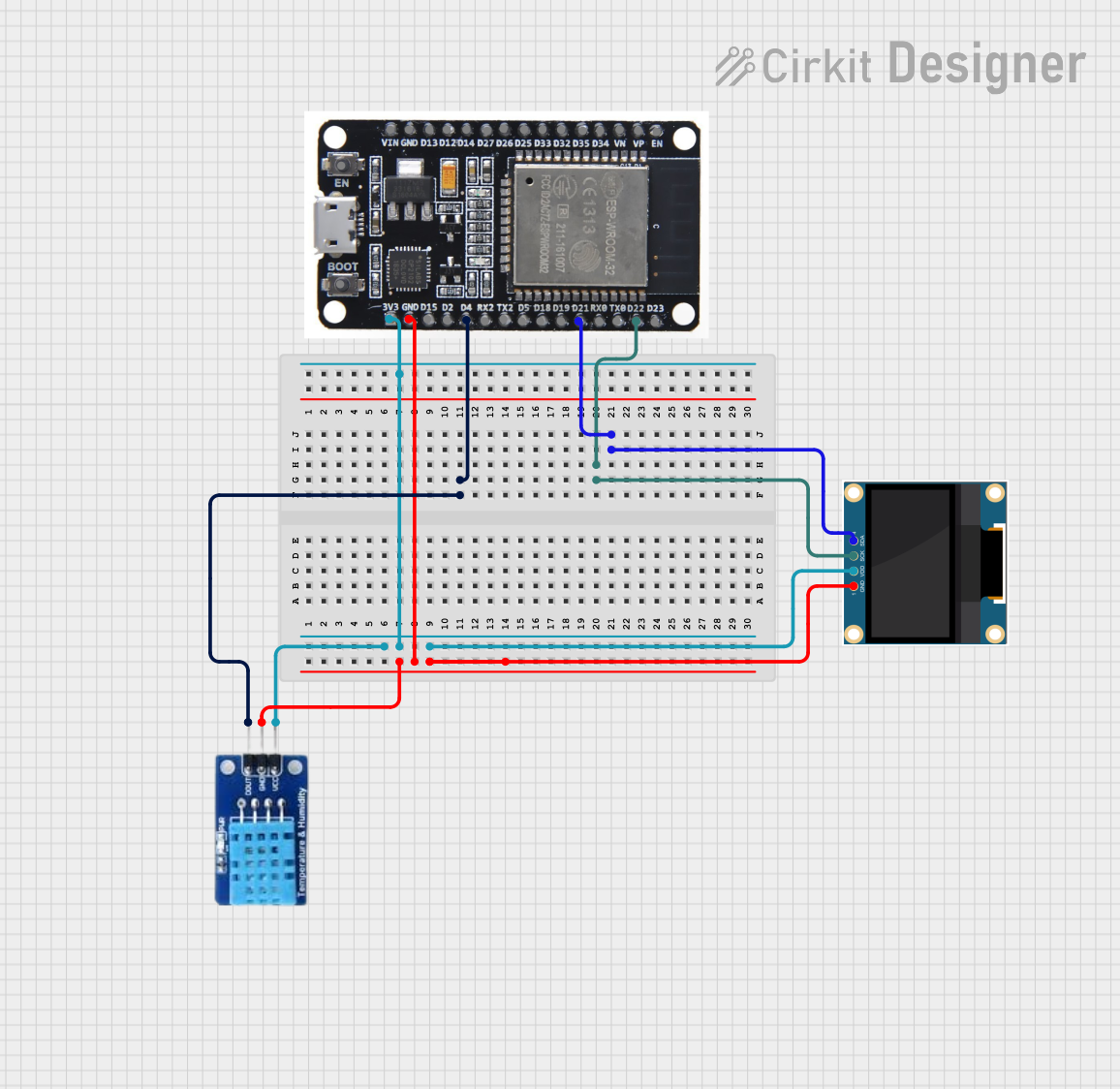
The circuit in question appears to be designed for environmental sensing and display purposes. It consists of an ESP32 microcontroller, which is a versatile and powerful module with Wi-Fi and Bluetooth capabilities. The ESP32 is connected to a 0.96" OLED display for visual output and a DHT11 sensor for measuring temperature and humidity. The ESP32 provides power to both the OLED display and the DHT11 sensor, and it communicates with the OLED display via I2C protocol (using SDA and SCK lines) and reads data from the DHT11 sensor through a single data line.
Component List
ESP32
- Description: A microcontroller with Wi-Fi and Bluetooth capabilities.
- Pins: EN, VP, VN, D34, D35, D32, D33, D25, D26, D27, D14, D12, D13, GND, VIN, 3V3, D15, D2, D4, RX2, TX2, D5, D18, D19, D21, RX0, TX0, D22, D23, BOOT
0.96" OLED
- Description: A small display for visual output.
- Pins: GND, VDD, SCK, SDA
DHT11
- Description: A sensor for measuring temperature and humidity.
- Pins: DATA, GND, VCC
Wiring Details
ESP32
- 3V3: Provides power to the OLED display (VDD) and the DHT11 sensor (VCC).
- GND: Connected to the ground pins of both the OLED display and the DHT11 sensor.
- D4: Connected to the DATA pin of the DHT11 sensor for data communication.
- D21 (SDA): Connected to the SDA pin of the OLED display for I2C data communication.
- D22 (SCK): Connected to the SCK pin of the OLED display for I2C clock signal.
0.96" OLED
- GND: Connected to the ground (GND) of the ESP32.
- VDD: Powered by the 3V3 output from the ESP32.
- SDA: Receives I2C data from the ESP32's D21 pin.
- SCK: Receives the I2C clock signal from the ESP32's D22 pin.
DHT11
- DATA: Sends data to the ESP32's D4 pin.
- GND: Connected to the ground (GND) of the ESP32.
- VCC: Powered by the 3V3 output from the ESP32.
Documented Code
No code has been provided for the microcontrollers in the circuit. To fully utilize the components in this circuit, embedded code for the ESP32 would be required to initialize and communicate with the DHT11 sensor and the OLED display. Typically, this would involve setting up the I2C communication for the OLED and reading the digital signal from the DHT11 sensor. Since no code is available, this section cannot be completed at this time.