
Arduino UNO-Based Air Quality and Temperature Monitoring System with LCD Display and Fan Control
View and Edit Project In Cirkit Designer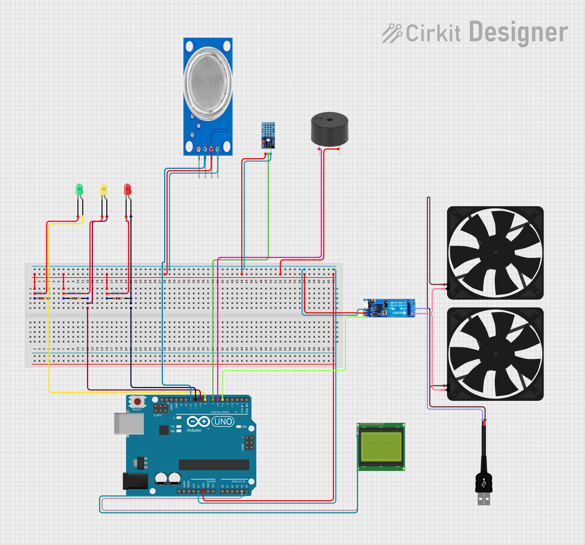
Circuit Documentation
Summary
This circuit involves an Arduino UNO microcontroller interfacing with various sensors, LEDs, a buzzer, a relay module, and a fan. The circuit is designed to monitor environmental conditions using the MQ135 gas sensor and DHT11 temperature and humidity sensor, display information on an LCD, and provide visual and auditory alerts using LEDs and a buzzer. The relay module controls the operation of two fans based on the sensor readings.
Component List
Arduino UNO
- Description: Microcontroller board based on the ATmega328P.
- Pins: UNUSED, IOREF, Reset, 3.3V, 5V, GND, Vin, A0, A1, A2, A3, A4, A5, SCL, SDA, AREF, D13, D12, D11, D10, D9, D8, D7, D6, D5, D4, D3, D2, D1, D0
MQ135
- Description: Gas sensor for detecting air quality.
- Pins: VCC, GND, A0, D0
Lcd 20x4 i2c
- Description: 20x4 character LCD with I2C interface.
- Pins: GND, 5V, SCA, SCL
LED: Two Pin (red)
- Description: Red LED.
- Pins: cathode, anode
LED: Two Pin (yellow)
- Description: Yellow LED.
- Pins: cathode, anode
LED: Two Pin (green)
- Description: Green LED.
- Pins: cathode, anode
Resistor (200 Ohms)
- Description: Resistor with 200 Ohms resistance.
- Pins: pin1, pin2
DHT 11
- Description: Temperature and humidity sensor.
- Pins: VCC, GND, DATA
Buzzer
- Description: Piezoelectric buzzer.
- Pins: PIN, GND
Fan
- Description: DC fan.
- Pins: GND, 5V
Relay module 5v-30v
- Description: Relay module for switching high voltage devices.
- Pins: common contact, normally open, normally closed, trigger, V-, V+
USB male 2 pin connection
- Description: USB male connector.
- Pins: Negative -, Positive +
Wiring Details
Arduino UNO
GND connected to:
- Resistor pin1 (green LED)
- Resistor pin1 (yellow LED)
- Resistor pin1 (red LED)
- MQ135 GND
- DHT 11 GND
- Buzzer GND
- Relay module V-
5V connected to:
- MQ135 VCC
- DHT 11 VCC
- Relay module V+
D8 connected to:
- Resistor pin2 (green LED)
- Green LED anode
D9 connected to:
- Resistor pin2 (yellow LED)
- Yellow LED anode
D10 connected to:
- Resistor pin2 (red LED)
- Red LED anode
A4 connected to:
- Lcd 20x4 i2c SCL
A5 connected to:
- Lcd 20x4 i2c SCA
D11 connected to:
- MQ135 A0
D7 connected to:
- DHT 11 DATA
D6 connected to:
- Buzzer PIN
D5 connected to:
- Relay module trigger
MQ135
- GND connected to Arduino UNO GND
- VCC connected to Arduino UNO 5V
- A0 connected to Arduino UNO D11
Lcd 20x4 i2c
- GND connected to Arduino UNO GND
- 5V connected to Arduino UNO 5V
- SCA connected to Arduino UNO A5
- SCL connected to Arduino UNO A4
LED: Two Pin (red)
- cathode connected to Resistor pin1
- anode connected to Resistor pin2 and Arduino UNO D10
LED: Two Pin (yellow)
- cathode connected to Resistor pin1
- anode connected to Resistor pin2 and Arduino UNO D9
LED: Two Pin (green)
- cathode connected to Resistor pin1
- anode connected to Resistor pin2 and Arduino UNO D8
Resistor (200 Ohms)
- pin1 connected to:
- Green LED cathode
- Yellow LED cathode
- Red LED cathode
- pin2 connected to:
- Green LED anode and Arduino UNO D8
- Yellow LED anode and Arduino UNO D9
- Red LED anode and Arduino UNO D10
DHT 11
- GND connected to Arduino UNO GND
- VCC connected to Arduino UNO 5V
- DATA connected to Arduino UNO D7
Buzzer
- GND connected to Arduino UNO GND
- PIN connected to Arduino UNO D6
Fan
- GND connected to:
- Relay module normally open
- 5V connected to:
- USB male 2 pin connection Positive +
Relay module 5v-30v
- V- connected to Arduino UNO GND
- V+ connected to Arduino UNO 5V
- trigger connected to Arduino UNO D5
- normally open connected to Fan GND
- common contact connected to USB male 2 pin connection Negative -
USB male 2 pin connection
- Negative - connected to Relay module common contact
- Positive + connected to Fan 5V
Code Documentation
Arduino UNO Code
void setup() {
  // put your setup code here, to run once:

}

void loop() {
  // put your main code here, to run repeatedly:

}
This code is a basic template for the Arduino UNO. The setup() function is used to initialize any settings or configurations, and the loop() function contains the main logic that runs repeatedly. Currently, both functions are empty and need to be populated with the specific logic for the circuit's operation.