
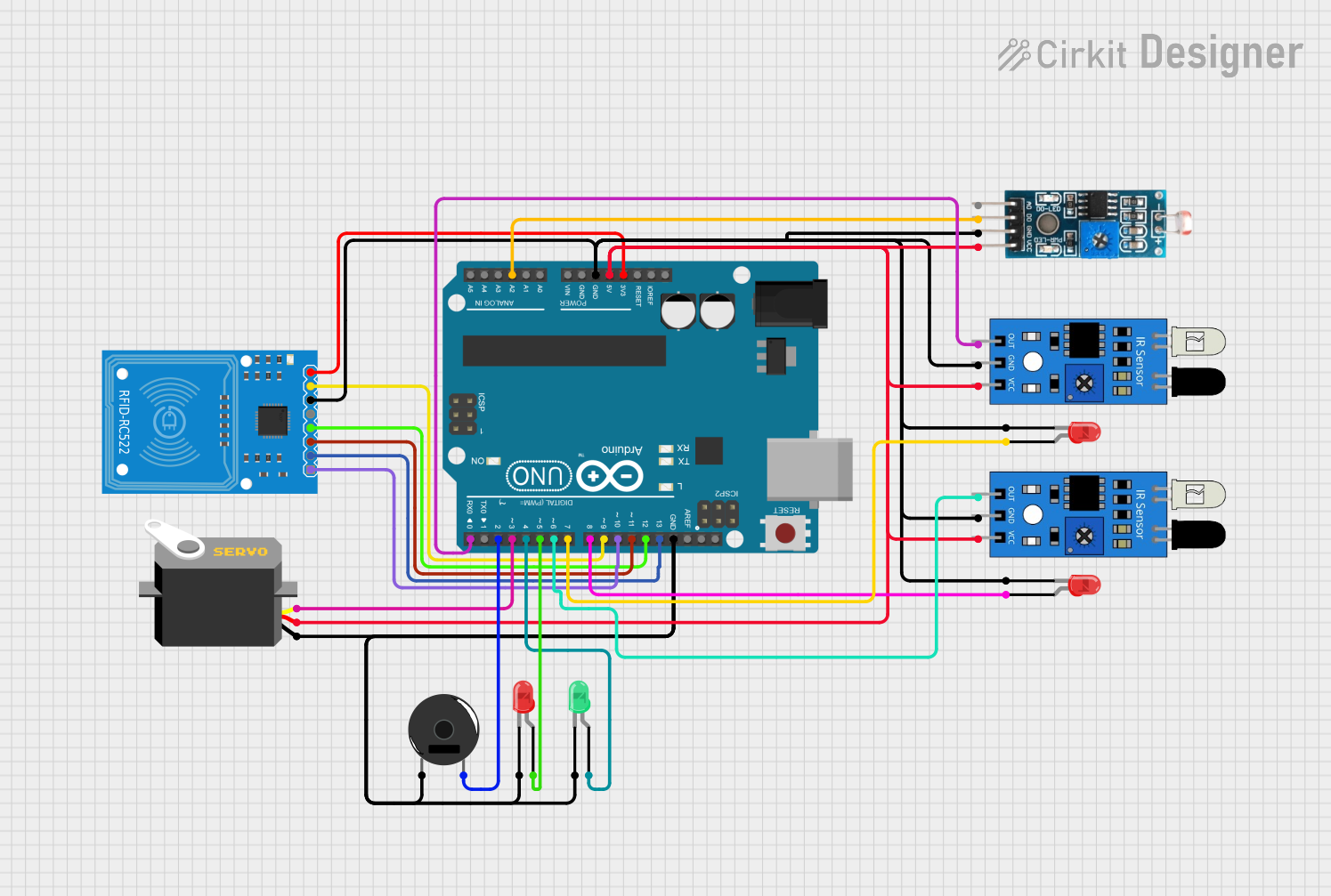
Circuit Documentation
Summary
This document provides a detailed overview of a circuit that includes an Arduino UNO as the central microcontroller interfaced with various peripherals including an RFID-RC522 module, a piezo buzzer, LEDs, servo motor, LDR module, and IR sensors. The circuit is designed to perform tasks that likely involve identification via RFID, light and motion detection, and visual and auditory signaling.
Component List
Arduino UNO
- Microcontroller board based on the ATmega328P
- It has 14 digital input/output pins, 6 analog inputs, a 16 MHz quartz crystal, a USB connection, a power jack, an ICSP header, and a reset button.
RFID-RC522
- A radio frequency identification (RFID) reader/writer module for NFC communication at 13.56 MHz.
Piezo Buzzer
- An electronic device that can be used to produce a tone, buzz, or beep of a particular frequency.
LEDs (Red and Green)
- Light Emitting Diodes that emit red and green light when powered.
Servo
- A rotary actuator or linear actuator that allows for precise control of angular or linear position, velocity, and acceleration.
Module LDR (Light Dependent Resistor)
- A sensor module that changes resistance with the change in the intensity of light falling on it.
IR Sensors
- Sensors that detect obstacles or movement based on infrared light detection.
Wiring Details
Arduino UNO
3.3Vconnected to RFID-RC5223.3V5Vconnected to Module LDRVCC, IR sensorsvcc, and ServovccGNDconnected to Module LDRGND, IR sensorsgnd, LEDscathode, RFID-RC522GND, Piezo Buzzerpin 1A2connected to Module LDRDOD13connected to RFID-RC522SCKD12connected to RFID-RC522MISOD11connected to RFID-RC522MOSID10connected to RFID-RC522SDAD9connected to RFID-RC522RSTD8connected to Red LEDanodeD7connected to Red LEDanodeD6connected to IR sensoroutD5connected to Red LEDanodeD4connected to Green LEDanodeD3connected to ServopulseD2connected to Piezo Buzzerpin 2D0connected to IR sensorout
RFID-RC522
3.3VandGNDfor power supplySCK,MISO,MOSI,SDA,RSTfor SPI communication with Arduino UNO
Piezo Buzzer
- One pin connected to Arduino UNO
D2 - Other pin connected to
GND
LEDs (Red and Green)
cathodeconnected toGNDanodeconnected to respective Arduino UNO digital pins (D8,D7,D5,D4)
Servo
gndconnected toGNDvccconnected to5Vpulseconnected to Arduino UNOD3
Module LDR
VCCconnected to5VGNDconnected toGNDDOconnected to Arduino UNOA2
IR Sensors
outconnected to Arduino UNOD6andD0gndconnected toGNDvccconnected to5V
Documented Code
void setup() {
  // put your setup code here, to run once:

}

void loop() {
  // put your main code here, to run repeatedly:

}
The provided code is a template with empty setup() and loop() functions, which are the standard structure for Arduino sketches. The setup() function is intended for code that needs to run once at the start, such as pin mode declarations. The loop() function is for code that continuously executes. Actual implementation details need to be filled in based on the specific requirements of the circuit's functionality.