Arduino Mega 2560-Based Ultrasonic Sensor Array with Bluetooth and Raspberry Pi Integration
Circuit Documentation
Summary
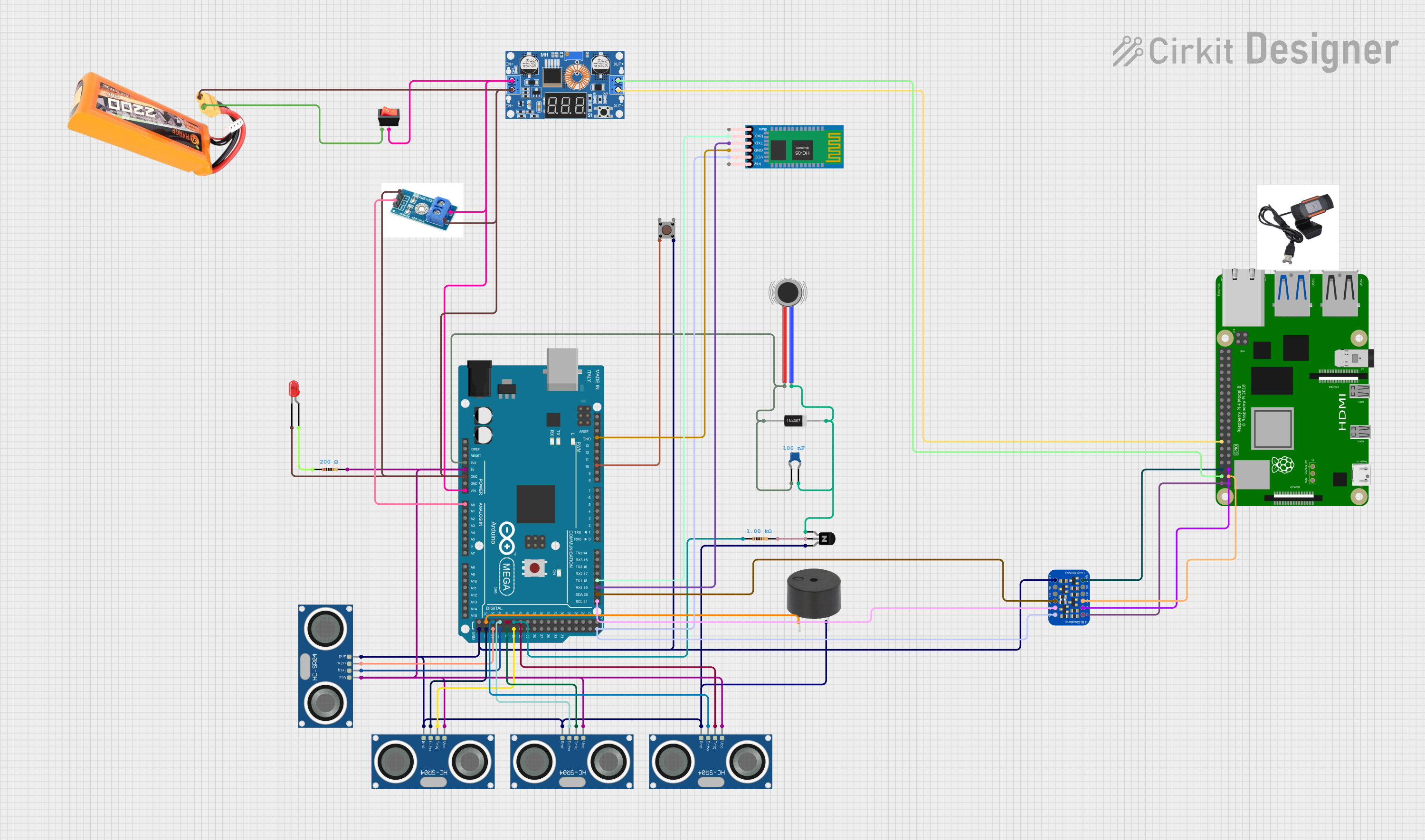
This circuit integrates a variety of components including an Arduino Mega 2560 microcontroller, multiple HC-SR04 Ultrasonic Sensors, a vibration motor, a diode, a capacitor, a transistor, resistors, a lipo battery, a rocker switch, a DC buck step-down converter, a DC voltage sensor, an LED, a pushbutton, a buzzer, an HC-05 Bluetooth module, a Raspberry Pi 4B, a logic level converter, and an HD webcam. The circuit is designed to interface with sensors, control actuators, and communicate with a Bluetooth module, while being powered by a lipo battery through a step-down converter. The Raspberry Pi 4B is included for more complex processing tasks, and the logic level converter ensures safe voltage levels between devices.
Component List
Microcontroller
- Arduino Mega 2560: A microcontroller board based on the ATmega2560 with numerous digital and analog I/O pins.
Sensors
- HC-SR04 Ultrasonic Sensors: Ultrasonic distance sensors that provide distance measurements via sonar.
Actuators
- Vibration Motor: A small motor that vibrates when powered.
- Buzzer: An electronic buzzer that emits sound when powered.
Power Components
- Lipo Battery 2200mAh 30C: A rechargeable battery that provides power to the circuit.
- XL4015 5A DC Buck Step-down: A voltage step-down module that converts higher voltage to a lower voltage.
- Rocker Switch: A switch that controls the connection of the circuit to the power source.
Signal Conditioning
- 1N4007 Rectifier Diode: A diode that allows current to flow in only one direction.
- Ceramic Capacitor: A small capacitor that can filter out voltage spikes.
- NPN Transistor (CBE): A transistor that can switch or amplify electronic signals.
- Resistors: Components that resist the flow of electric current.
Communication Modules
- HC-05 Bluetooth Module: A Bluetooth module for wireless communication.
Interface and Conversion
- Adafruit 4-channel I2C-safe Bi-directional Logic Level Converter: A device that safely steps down 5V signals to 3.3V and steps up 3.3V to 5V.
Indicators
- LED (Red): A light-emitting diode that illuminates when powered.
Control and User Interface
- Pushbutton: A button that can be used to trigger events in the circuit.
Processing
- Raspberry Pi 4B: A small computer that can handle complex processing tasks.
Miscellaneous
- HD Webcam: A high-definition camera for capturing video.
Wiring Details
Arduino Mega 2560
- 3V3: Connected to the anode of the 1N4007 Rectifier Diode, Ceramic Capacitor, and Vibration Motor's positive terminal.
- 5V: Powers the HC-SR04 Ultrasonic Sensors and the logic level converter's HV pin.
- GND: Common ground for various components including the XL4015 step-down converter's input, DC voltage sensor, LED, HC-05 Bluetooth module, and others.
- VIN: Connected to the output of the rocker switch.
- A0: Receives analog input from the DC voltage sensor.
- D21/SCL, D20/SDA: Connected to the logic level converter for I2C communication.
- D19/RX1, D18/TX1: Serial communication with the HC-05 Bluetooth module.
- D10 PWM: Connected to the pushbutton.
- D52, D50, D48, D46, D44: Control and receive signals from the HC-SR04 Ultrasonic Sensors and the buzzer.
- D53, D51, D49, D47, D45: Additional control pins for the HC-SR04 Ultrasonic Sensors.
HC-SR04 Ultrasonic Sensors
- VCC: Powered by the Arduino's 5V pin.
- TRIG: Trigger pins connected to various digital pins on the Arduino.
- ECHO: Echo pins connected to various digital pins on the Arduino.
- GND: Connected to the common ground.
Vibration Motor
- POS: Connected to the 3V3 pin of the Arduino.
- NEG: Connected to the cathode of the 1N4007 Rectifier Diode.
1N4007 Rectifier Diode
- Anode: Connected to the 3V3 pin of the Arduino.
- Cathode: Connected to the negative terminal of the Vibration Motor and the collector of the NPN Transistor.
Ceramic Capacitor
- pin0: Connected to the 3V3 pin of the Arduino.
- pin1: Connected to the cathode of the 1N4007 Rectifier Diode.
NPN Transistor (CBE)
- collector: Connected to the cathode of the 1N4007 Rectifier Diode.
- base: Connected to a resistor.
- emitter: Connected to the common ground.
Resistors
- 1kΩ and 200Ω resistors: Used for current limiting and voltage division in various parts of the circuit.
Lipo Battery 2200mAh 30C
- VCC: Provides power to the rocker switch.
- GND: Connected to the common ground.
Rocker Switch
- input: Connected to the VCC of the lipo battery.
- output: Connected to the VIN of the Arduino and the input of the XL4015 step-down converter.
XL4015 5A DC Buck Step-down
- Input +: Connected to the output of the rocker switch.
- Input -: Connected to the common ground.
- Output +: Powers the Raspberry Pi 4B's 5V pin.
- Output -: Connected to the Raspberry Pi 4B's ground.
DC VOLTAGE SENSOR
- GND: Connected to the common ground.
- Vin: Connected to the input of the XL4015 step-down converter.
- S: Sends analog voltage level to the Arduino's A0 pin.
LED (Red)
- cathode: Connected to the common ground.
- anode: Connected to a 200Ω resistor.
Pushbutton
- Pin 2 (in): Connected to the D10 PWM pin of the Arduino.
- Pin 4 (out): Connected to the common ground.
Buzzer
- PIN: Connected to the D52 pin of the Arduino.
- GND: Connected to the common ground.
HC-05 Bluetooth Module
- Key, State: Not connected in the provided net list.
- VCC: Powered by the logic level converter's HV pin.
- GND: Connected to the common ground.
- TXD: Connected to the D19/RX1 pin of the Arduino.
- RXD: Connected to the D18/TX1 pin of the Arduino.
Raspberry Pi 4B
- 5V: Powered by the output of the XL4015 step-down converter.
- 3V3: Connected to the LV pin of the logic level converter.
- GPIO2, GPIO3: Connected to the A2 and A1 pins of the logic level converter, respectively.
- GND: Connected to the common ground.
Adafruit 4-channel I2C-safe Bi-directional Logic Level Converter
- GND: Connected to the common ground.
- A4, A3, A2, A1: Connected to the Raspberry Pi GPIOs and the Arduino I2C pins.
- LV: Connected to the 3V3 pin of the Raspberry Pi.
- B4, B3, B2, B1: Connected to the Arduino I2C pins.
- HV: Connected to the 5V pin of the Arduino.
HD Webcam
- D, S: Not connected in the provided net list.
Documented Code
Arduino Mega 2560 Code (sketch.ino)
void setup() {
  // put your setup code here, to run once:

}

void loop() {
  // put your main code here, to run repeatedly:

}
Note: The provided code for the Arduino Mega 2560 is a template with empty setup and loop functions. The actual functionality needs to be implemented based on the requirements of the circuit.