
Arduino-Controlled NEMA 17 Stepper Motor with OLED Display and Keypad Interface
View and Edit Project In Cirkit Designer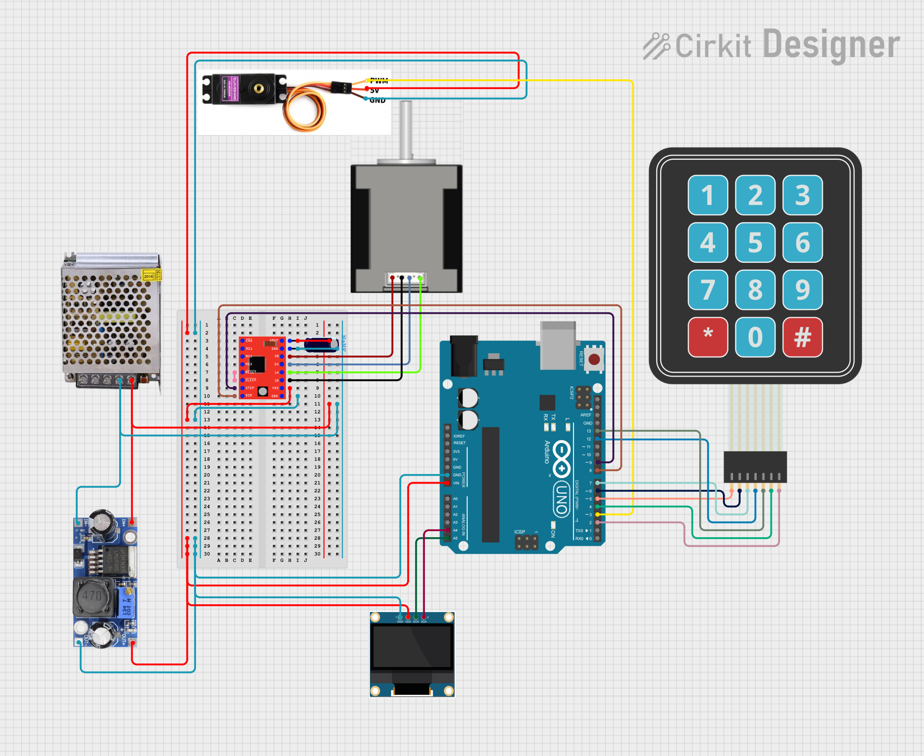
Circuit Documentation
Summary of the Circuit
This circuit is designed to control a NEMA 17 stepper motor using an A4988 stepper motor driver, with an Arduino UNO as the main microcontroller. The circuit includes a power supply that provides 12V to the motor driver and a DC-DC converter to step down the voltage for other components. A servo motor and an OLED display are also interfaced with the Arduino for additional functionality. User inputs are captured through a membrane matrix keypad. The circuit is designed to be modular, with the capability to expand or modify for different applications.
Component List
Arduino UNO
- Microcontroller board based on the ATmega328P
- Used as the main controller for the circuit
POWER SUPPLY 12V 5AMP
- Provides the main power source for the circuit
- Outputs 12V DC for the motor driver and other components
DC DC Converter
- Steps down the voltage from 12V to a lower voltage suitable for logic level components
NEMA 17 HS4401
- A stepper motor used for precision control of movement
Servo Motor MG996R
- A servo motor used for angular positioning
A4988 Stepper Motor Driver (Red)
- Interfaces with the NEMA 17 stepper motor to control its movements
0.96" OLED
- A small display to provide user feedback or display status messages
Membrane Matrix Keypad
- A simple interface for user input
Electrolytic Capacitor
- Used for filtering and stabilizing the power supply to the motor driver
Wiring Details
Arduino UNO
D9connected to A4988STEPfor stepping signalD8connected to A4988DIRfor direction controlA4connected to OLEDSDAfor I2C dataA5connected to OLEDSCLfor I2C clockD13connected to KeypadColumn 1D12connected to KeypadRow 4D7connected to KeypadRow 3D6connected to KeypadRow 2D5connected to KeypadRow 1D4connected to KeypadColumn 2D3connected to ServoPMWD2connected to KeypadColumn 3GNDconnected to common ground netVinconnected to DC DC converter+VCC OUTfor power
POWER SUPPLY 12V 5AMP
12V-24V Output (DC)connected to A4988VMOTand DC DC converter+VCC INGND (DC)connected to common ground net
DC DC Converter
+VCC OUTconnected to ArduinoVin, A4988VDD, ServoVCC 5V, and OLEDVDDGND OUTconnected to common ground net
NEMA 17 HS4401
RED (B2)connected to A49882BBLACK (B1)connected to A49881BBLUE (A2)connected to A49882AGREEN (A1)connected to A49881A
Servo Motor MG996R
PMWconnected to ArduinoD3VCC 5Vconnected to A4988VDDGNDconnected to common ground net
A4988 Stepper Motor Driver (Red)
VMOTconnected to power supply12V-24V Output (DC)GNDconnected to common ground net2B,2A,1A,1Bconnected to corresponding NEMA 17 motor pinsRESETconnected toSLEEPfor enabling the driverSTEPconnected to ArduinoD9DIRconnected to ArduinoD8VDDconnected to DC DC converter+VCC OUT
0.96" OLED
GNDconnected to common ground netVDDconnected to DC DC converter+VCC OUTSCLconnected to ArduinoA5SDAconnected to ArduinoA4
Membrane Matrix Keypad
Row 1toRow 4connected to ArduinoD5toD12Column 1toColumn 3connected to ArduinoD13toD2
Electrolytic Capacitor
+connected to A4988GND-connected to power supply12V-24V Output (DC)
Documented Code
Arduino UNO Code (sketch.ino)
void setup() {
  // put your setup code here, to run once:

}

void loop() {
  // put your main code here, to run repeatedly:

}
Note: The provided code is a template and does not include specific functionality. It should be expanded to initialize the connected components and implement the desired behavior of the circuit.