
Arduino UNO-Based Line Following and Obstacle Avoidance Robot with Ultrasonic and IR Sensors
View and Edit Project In Cirkit Designer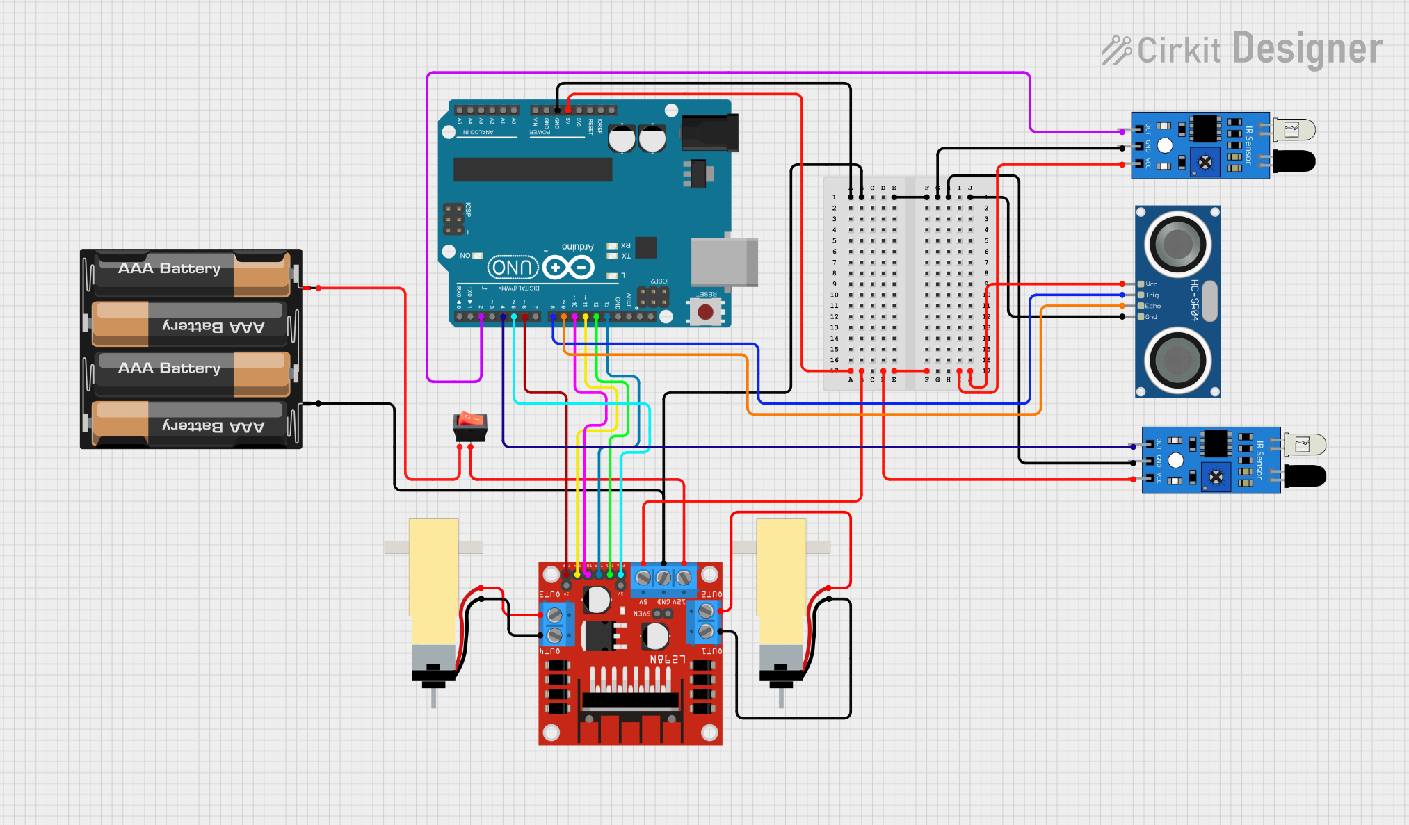
Circuit Documentation
Summary
This document provides a detailed overview of a circuit designed to control a robot using an Arduino UNO microcontroller. The robot is equipped with an HC-SR04 ultrasonic sensor for obstacle detection, two IR sensors for line following, and two hobby gearmotors controlled by an L298N DC motor driver. The circuit is powered by a 4 x AAA battery mount and includes a rocker switch for power control.
Component List
4 x AAA Battery Mount
- Description: Provides power to the circuit.
- Pins:
-,+
HC-SR04 Ultrasonic Sensor
- Description: Measures distance to obstacles.
- Pins:
VCC,TRIG,ECHO,GND
Arduino UNO
- Description: Microcontroller that controls the robot.
- Pins:
UNUSED,IOREF,Reset,3.3V,5V,GND,Vin,A0,A1,A2,A3,A4,A5,SCL,SDA,AREF,D13,D12,D11,D10,D9,D8,D7,D6,D5,D4,D3,D2,D1,D0
IR Sensor (Left)
- Description: Detects the line for line following.
- Pins:
out,gnd,vcc
IR Sensor (Right)
- Description: Detects the line for line following.
- Pins:
out,gnd,vcc
L298N DC Motor Driver
- Description: Controls the speed and direction of the motors.
- Pins:
OUT1,OUT2,12V,GND,5V,OUT3,OUT4,5V-ENA-JMP-I,5V-ENA-JMP-O,+5V-J1,+5V-J2,ENA,IN1,IN2,IN3,IN4,ENB
Rocker Switch
- Description: Controls the power to the circuit.
- Pins:
output,input
Hobby Gearmotor with 48:1 Gearbox (Left)
- Description: Drives the left wheel of the robot.
- Pins:
pin 1,pin 2
Hobby Gearmotor with 48:1 Gearbox (Right)
- Description: Drives the right wheel of the robot.
- Pins:
pin 1,pin 2
Wiring Details
4 x AAA Battery Mount
- -: Connected to
GNDof L298N DC motor driver, IR sensors, Arduino UNO, and HC-SR04 Ultrasonic Sensor. - +: Connected to
inputof Rocker Switch.
HC-SR04 Ultrasonic Sensor
- VCC: Connected to
5Vof Arduino UNO. - TRIG: Connected to
D8of Arduino UNO. - ECHO: Connected to
D9of Arduino UNO. - GND: Connected to
GNDof Arduino UNO.
Arduino UNO
- 5V: Connected to
5Vof L298N DC motor driver and IR sensors. - GND: Connected to
GNDof L298N DC motor driver, IR sensors, and HC-SR04 Ultrasonic Sensor. - D8: Connected to
TRIGof HC-SR04 Ultrasonic Sensor. - D9: Connected to
ECHOof HC-SR04 Ultrasonic Sensor. - D13: Connected to
IN2of L298N DC motor driver. - D12: Connected to
IN1of L298N DC motor driver. - D11: Connected to
IN4of L298N DC motor driver. - D10: Connected to
IN3of L298N DC motor driver. - D6: Connected to
ENBof L298N DC motor driver. - D5: Connected to
ENAof L298N DC motor driver. - D4: Connected to
outof Left IR Sensor. - D2: Connected to
outof Right IR Sensor.
IR Sensor (Left)
- out: Connected to
D4of Arduino UNO. - gnd: Connected to
GNDof Arduino UNO. - vcc: Connected to
5Vof Arduino UNO.
IR Sensor (Right)
- out: Connected to
D2of Arduino UNO. - gnd: Connected to
GNDof Arduino UNO. - vcc: Connected to
5Vof Arduino UNO.
L298N DC Motor Driver
- GND: Connected to
GNDof Arduino UNO and Battery Mount. - 5V: Connected to
5Vof Arduino UNO. - IN2: Connected to
D13of Arduino UNO. - IN1: Connected to
D12of Arduino UNO. - IN4: Connected to
D11of Arduino UNO. - IN3: Connected to
D10of Arduino UNO. - ENB: Connected to
D6of Arduino UNO. - ENA: Connected to
D5of Arduino UNO. - OUT1: Connected to
pin 1of Right Hobby Gearmotor. - OUT2: Connected to
pin 2of Right Hobby Gearmotor. - OUT3: Connected to
pin 2of Left Hobby Gearmotor. - OUT4: Connected to
pin 1of Left Hobby Gearmotor. - 12V: Connected to
outputof Rocker Switch.
Rocker Switch
- input: Connected to
+of Battery Mount. - output: Connected to
12Vof L298N DC motor driver.
Hobby Gearmotor with 48:1 Gearbox (Left)
- pin 1: Connected to
OUT4of L298N DC motor driver. - pin 2: Connected to
OUT3of L298N DC motor driver.
Hobby Gearmotor with 48:1 Gearbox (Right)
- pin 1: Connected to
OUT1of L298N DC motor driver. - pin 2: Connected to
OUT2of L298N DC motor driver.
Documented Code
Arduino UNO Code
// Define pins for motor speed control (EnA and EnB)
int VelocidadMotor1 = 6;
int VelocidadMotor2 = 5;

// Define control pins for motor direction (In1, In2, In3, In4)
int Motor1A = 13;
int Motor1B = 12;
int Motor2C = 11;
int Motor2D = 10;

// Infrared sensors - left and right
int infraPin = 2; // Right IR sensor
int infraPin1 = 4; // Left IR sensor

// Variables to capture sensor values: 0 - light background, 1 - black line
int valorInfra = 0;
int valorInfra1 = 0;

// Ultrasonic sensor pins
#define PIN_TRIG 9
#define PIN_ECHO 8

long duration, distance;

// Initial setup
void setup() {
    Serial.begin(9600);
    delay(1000);
    // Configure ultrasonic sensor
    pinMode(PIN_TRIG, OUTPUT);
    pinMode(PIN_ECHO, INPUT);
    // Set up IR sensor pins
    pinMode(infraPin, INPUT);
    pinMode(infraPin1, INPUT);

    // Set up motor control pins
    pinMode(Motor1A, OUTPUT);
    pinMode(Motor1B, OUTPUT);
    pinMode(Motor2C, OUTPUT);
    pinMode(Motor2D, OUTPUT);
    pinMode(VelocidadMotor1, OUTPUT);
    pinMode(VelocidadMotor2, OUTPUT);

    // Set initial motor speeds
    analogWrite(VelocidadMotor1, 150);
    analogWrite(VelocidadMotor2, 180);

    // Initialize motor direction
    digitalWrite(Motor1A, LOW);
    digitalWrite(Motor1B, LOW);
    digitalWrite(Motor2C, LOW);
    digitalWrite(Motor2D, LOW);
}

// Main loop
void loop() {
    // Ultrasonic sensor measurement
    digitalWrite(PIN_TRIG, LOW);
    delayMicroseconds(5);
    digitalWrite(PIN_TRIG, HIGH);
    delayMicroseconds(10);
    digitalWrite(PIN_TRIG, LOW);
    duration = pulseIn(PIN_ECHO, HIGH);
    distance = (duration / 2) / 29.1; // Convert time to distance in cm
    Serial.print("Distance to object: ");