
Solar-Powered Battery Management System with Wi-Fi Connectivity and Environmental Sensing
View and Edit Project In Cirkit Designer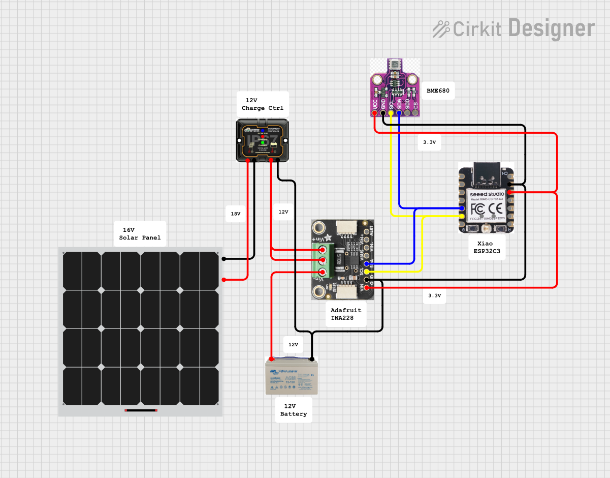
Solar-Powered Environmental Monitoring System Documentation
Summary
This document outlines the design and functionality of a solar-powered environmental monitoring system. The system is designed to be energy-efficient and self-sustaining, utilizing a solar panel to charge a battery which in turn powers the monitoring hardware. The core components include a solar panel, a Maximum Power Point Tracking (MPPT) charge controller, a 12V battery, an Adafruit INA228 high-side measurement breakout board for voltage and current monitoring, a Xiao ESP32-C3 microcontroller for data processing and communication, and a BME680 sensor for environmental data collection.
Component List
Solar Panel
- Description: A photovoltaic panel that converts sunlight into electrical energy.
- Purpose: To provide a renewable energy source for charging the battery.
MPPT 12V Charge Controller
- Description: A charge controller that optimizes the power output from the solar panel to charge the battery efficiently.
- Purpose: To manage the charging of the battery and protect it from overcharging.
12V AGM Battery
- Description: A 12V Absorbent Glass Mat (AGM) battery that stores electrical energy.
- Purpose: To supply power to the system when solar energy is insufficient.
Adafruit INA228
- Description: A high-side measurement breakout board capable of measuring voltage and current.
- Purpose: To monitor the power consumption and charging status of the system.
Xiao ESP32-C3
- Description: A microcontroller with Wi-Fi and Bluetooth capabilities.
- Purpose: To process sensor data, control the system, and communicate with external devices or servers.
BME680
- Description: An environmental sensor that measures temperature, humidity, pressure, and gas.
- Purpose: To collect environmental data for monitoring purposes.
Wiring Details
Solar Panel
- Positive (+) connected to the positive input of the MPPT 12V Charge Controller.
- Negative (-) connected to the negative input of the MPPT 12V Charge Controller.
MPPT 12V Charge Controller
- Positive (+) connected to the positive terminal of the 12V AGM Battery and the VBUS and Vin+ pins of the Adafruit INA228.
- Negative (-) connected to the negative terminal of the 12V AGM Battery and the GND pins of the Adafruit INA228, BME680, and Xiao ESP32-C3.
12V AGM Battery
- Positive (+) connected to the Vin- pin of the Adafruit INA228.
- Negative (-) connected to the GND pins of the Adafruit INA228, BME680, and Xiao ESP32-C3.
Adafruit INA228
- VIN connected to the 3V3 pin of the Xiao ESP32-C3 and the VCC pin of the BME680.
- GND connected to the GND pins of the BME680 and Xiao ESP32-C3.
- SCL connected to the SCL pins of the BME680 and the GPIO7/SCL/D5 pin of the Xiao ESP32-C3.
- SDA connected to the SDA pins of the BME680 and the GPIO6/SDA/D4 pin of the Xiao ESP32-C3.
Xiao ESP32-C3
- 3V3 connected to the VIN pin of the Adafruit INA228 and the VCC pin of the BME680.
- GND connected to the GND pins of the Adafruit INA228 and BME680.
- GPIO7/SCL/D5 connected to the SCL pins of the Adafruit INA228 and BME680.
- GPIO6/SDA/D4 connected to the SDA pins of the Adafruit INA228 and BME680.
BME680
- VCC connected to the VIN pin of the Adafruit INA228 and the 3V3 pin of the Xiao ESP32-C3.
- GND connected to the GND pins of the Adafruit INA228 and Xiao ESP32-C3.
- SCL connected to the SCL pin of the Adafruit INA228 and the GPIO7/SCL/D5 pin of the Xiao ESP32-C3.
- SDA connected to the SDA pin of the Adafruit INA228 and the GPIO6/SDA/D4 pin of the Xiao ESP32-C3.
Documented Code
Xiao ESP32-C3 Microcontroller Code (sketch.ino)
void setup() {
  // put your setup code here, to run once:

}

void loop() {
  // put your main code here, to run repeatedly:

}
Note: The provided code is a template and does not contain any functional implementation. The setup function is intended for initialization code that runs once at startup, and the loop function is for code that runs continuously in the main program loop. Additional code is required to initialize and read from the BME680 sensor, manage power with the Adafruit INA228, and handle communication for data reporting.