
Arduino Mega 2560-Based Biometric and Health Monitoring System with WiFi Connectivity
View and Edit Project In Cirkit Designer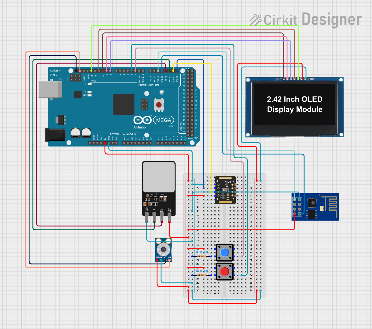
Circuit Documentation
Summary
This circuit integrates various components including sensors, a microcontroller, a display, and a WiFi module to create a multifunctional system. The Arduino Mega 2560 serves as the central processing unit, interfacing with a fingerprint scanner, an OLED display, an ESP8266 WiFi module, temperature sensor (mlx90614), a pulse oximetry sensor (MAX30102), and two pushbuttons with pull-up resistors. The system is designed to collect and process data from the sensors, interact with the user through the pushbuttons and display, and communicate wirelessly via the ESP8266 module.
Component List
Fingerprint Scanner
- Pins: VCC, TX, RX, GND
- Description: Used for biometric identification.
Arduino Mega 2560
- Pins: Multiple digital and analog pins, power, and communication interfaces.
- Description: Acts as the central microcontroller for the circuit.
OLED Display 2.42"
- Pins: GND, VCC, SCK, SDA, RES, DC, CS
- Description: Displays information to the user.
ESP8266 ESP-01 WiFi Module
- Pins: TXD, CH_PD, RST, VCC, GND, GPIO_2, GPIO_0, RXD
- Description: Provides wireless communication capabilities.
Pushbutton (x2)
- Pins: Pin 2, Pin 1, Pin 3, Pin 4
- Description: User input devices.
Resistor (x2)
- Pins: pin1, pin2
- Description: 10k Ohm pull-up resistors for the pushbuttons.
mlx90614
- Pins: SDA, SCL, GND, VIN
- Description: Infrared thermometer for non-contact temperature measurements.
MAX30102
- Pins: VIN, SDA, SCL, GND, RD, IRD, INT
- Description: Pulse oximetry and heart-rate sensor.
Wiring Details
Fingerprint Scanner
- VCC: Connected to 5V power supply.
- TX: Connected to Arduino Mega 2560 (D18/TX1).
- RX: Connected to Arduino Mega 2560 (D19/RX1).
- GND: Connected to common ground.
Arduino Mega 2560
- GND: Common ground for all components.
- 5V: Power supply for components requiring 5V.
- Various I/O Pins: Connected to corresponding components for data transfer and control.
OLED Display 2.42"
- GND: Connected to common ground.
- VCC: Connected to 5V power supply.
- SCK: Connected to Arduino Mega 2560 (D13 PWM).
- SDA: Connected to Arduino Mega 2560 (D11 PWM).
- RES: Connected to Arduino Mega 2560 (D8 PWM).
- DC: Connected to Arduino Mega 2560 (D9 PWM).
- CS: Connected to Arduino Mega 2560 (D10 PWM).
ESP8266 ESP-01 WiFi Module
- TXD: Connected to Arduino Mega 2560 (D16 PWM/TX2).
- RXD: Connected to Arduino Mega 2560 (D17 PWM/RX2).
- VCC: Connected to 5V power supply.
- GND: Connected to common ground.
Pushbuttons
- Pin 2: Connected to Arduino Mega 2560 (D2 PWM and D3 PWM respectively).
- Pin 1: Connected to one side of the 10k Ohm resistors.
- Pin 4: Connected to 5V power supply.
- Pin 3: Not connected.
Resistor (10k Ohm)
- pin1: Connected to GND.
- pin2: Connected to Pushbutton Pin 1.
mlx90614
- SDA: Connected to Arduino Mega 2560 (SDA).
- SCL: Connected to Arduino Mega 2560 (SCL).
- GND: Connected to common ground.
- VIN: Connected to 5V power supply.
MAX30102
- VIN: Connected to 5V power supply.
- SDA: Connected to Arduino Mega 2560 (D20/SDA).
- SCL: Connected to Arduino Mega 2560 (D21/SCL).
- GND: Connected to common ground.
Documented Code
Arduino Mega 2560 Code (sketch.ino)
void setup() {
  // put your setup code here, to run once:

}

void loop() {
  // put your main code here, to run repeatedly:

}
Note: The provided code is a template and does not include specific functionality. It should be expanded to initialize the connected components and handle the desired operations of the circuit.