
Raspberry Pi Pico W Controlled Multi-IR Sensor Array with RGB LED Feedback and Motor Driver
View and Edit Project In Cirkit Designer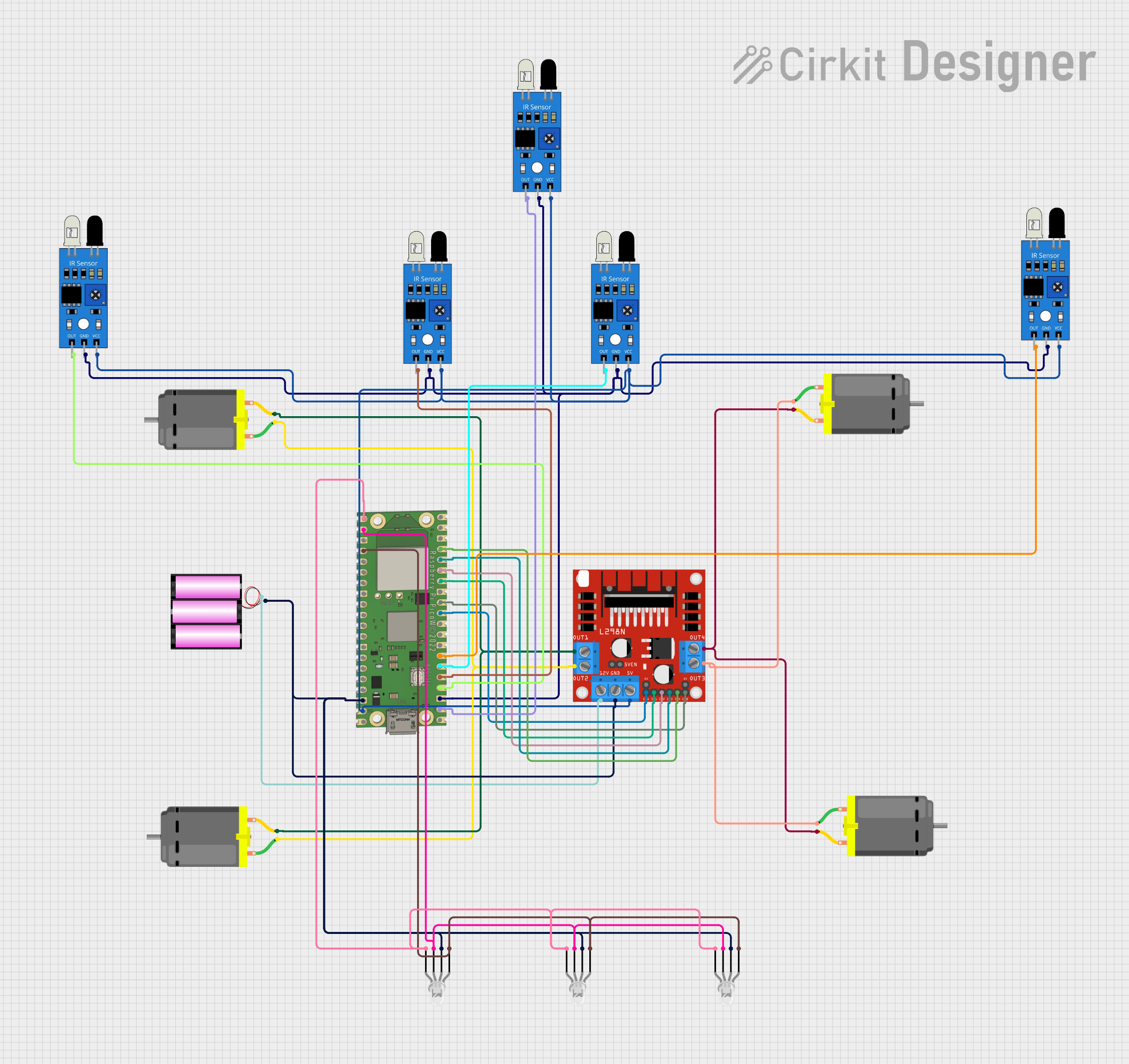
Circuit Documentation
Summary
The circuit in question is designed to interface a Raspberry Pi Pico W with multiple IR sensors, a set of RGB LEDs, and DC motors through an L298N motor driver. The Raspberry Pi Pico W serves as the central processing unit, controlling the IR sensors and the RGB LEDs, as well as driving the motors via the motor driver. The IR sensors are likely used for detecting objects or motion, while the RGB LEDs could be used for status indication. The DC motors are controlled in terms of direction and speed by the L298N motor driver, which receives commands from the Raspberry Pi Pico W.
Component List
Raspberry Pi Pico W
- Microcontroller board with WiFi capabilities.
- Pins: VBUS, VSYS, GP16-GP22, RUN, GP26-GP28, ADC_VREF, 3V3 OUT, 3V3_EN, GP0-GP15.
IR Sensors
- Used for object detection or motion sensing.
- Pins: out, gnd, vcc.
L298N DC Motor Driver
- Module for controlling the direction and speed of DC motors.
- Pins: OUT1-OUT4, 12V, GND, 5V, 5V-ENA-JMP-I/O, +5V-J1/J2, ENA, ENB, IN1-IN4.
DC Motors
- Actuators for motion in the circuit.
- Pins: pin 1, pin 2.
Battery 12V
- Power source for the motor driver and motors.
- Pins: +, -.
RGB LEDs (Common Cathode)
- Used for status indication or signaling.
- Pins: red anode, common cathode, green anode, blue anode.
Comment
- A placeholder for additional notes or comments in the circuit.
Wiring Details
Raspberry Pi Pico W
- VSYS connected to IR sensors' VCC and L298N's 5V.
- GND connected to IR sensors' GND, L298N's GND, RGB LEDs' common cathode, and Battery 12V's -.
- GP16 connected to RGB LEDs' blue anode.
- GP17 connected to RGB LEDs' green anode.
- GP18 connected to RGB LEDs' red anode.
- GP1, GP2, GP3, GP4, GP5 connected to IR sensors' out.
- GP8, GP9 connected to L298N's ENA, ENB.
- GP10-GP13 connected to L298N's IN1-IN4.
IR Sensors
- VCC connected to Raspberry Pi Pico W's VSYS.
- GND connected to Raspberry Pi Pico W's GND.
- Out connected to Raspberry Pi Pico W's GP1, GP2, GP3, GP4, GP5.
L298N DC Motor Driver
- 5V connected to Raspberry Pi Pico W's VSYS.
- GND connected to Raspberry Pi Pico W's GND and RGB LEDs' common cathode.
- IN1-IN4 connected to Raspberry Pi Pico W's GP10-GP13.
- ENA, ENB connected to Raspberry Pi Pico W's GP8, GP9.
- OUT1-OUT4 connected to DC Motors' pins.
- 12V connected to Battery 12V's +.
DC Motors
- Pin 1 and Pin 2 connected to L298N's OUT1-OUT4.
Battery 12V
-
- connected to L298N's 12V.
-
- connected to Raspberry Pi Pico W's GND and RGB LEDs' common cathode.
RGB LEDs (Common Cathode)
- Red anode connected to Raspberry Pi Pico W's GP18.
- Green anode connected to Raspberry Pi Pico W's GP17.
- Blue anode connected to Raspberry Pi Pico W's GP16.
- Common cathode connected to Raspberry Pi Pico W's GND, L298N's GND, and Battery 12V's -.
Documented Code
No code was provided for the microcontrollers in the circuit. The expected code would likely include initialization of GPIO pins, PWM setup for motor speed control, digital read for IR sensor input, and digital write for LED control. Without the actual code, we cannot provide further documentation on the software aspect of this circuit.