
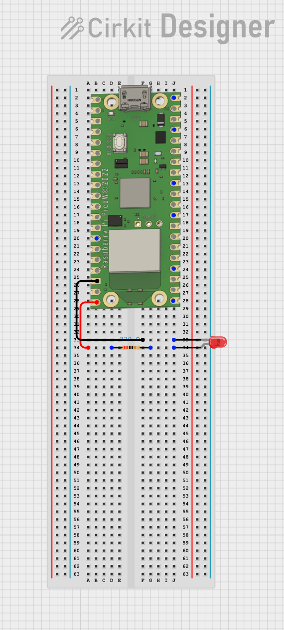
Circuit Documentation
Summary
This document provides a detailed description of a simple circuit involving a Raspberry Pi Pico W microcontroller, a red LED, and a resistor. The circuit is designed to control the LED using one of the GPIO pins on the Raspberry Pi Pico W.
Component List
Raspberry Pi Pico W
- Description: A microcontroller board based on the RP2040 microcontroller chip.
- Pins: VBUS, VSYS, GP16, GP17, GND, GP18, GP19, GP20, GP21, GP22, RUN, GP26, GP27, GP28, ADC_VREF, 3V3 OUT, 3V3_EN, GP0, GP1, GP2, GP3, GP4, GP5, GP6, GP7, GP15, GP14, GP13, GP12, GP11, GP10, GP9, GP8
LED: Two Pin (red)
- Description: A standard red LED with two pins: anode and cathode.
- Pins: cathode, anode
Resistor
- Description: A resistor with a resistance of 220 Ohms.
- Pins: pin1, pin2
- Properties:
- Resistance: 220 Ohms
Wiring Details
Raspberry Pi Pico W
- GND is connected to the cathode of the red LED.
- GP15 is connected to pin1 of the resistor.
LED: Two Pin (red)
- cathode is connected to GND of the Raspberry Pi Pico W.
- anode is connected to pin2 of the resistor.
Resistor
- pin1 is connected to GP15 of the Raspberry Pi Pico W.
- pin2 is connected to the anode of the red LED.
Code
There is no code provided for this circuit.
This document provides a comprehensive overview of the components and their connections in the circuit. The Raspberry Pi Pico W controls the LED through a GPIO pin, with a resistor in series to limit the current.