
Arduino Nano Solar-Powered Light-Dependent Servo Control System
View and Edit Project In Cirkit Designer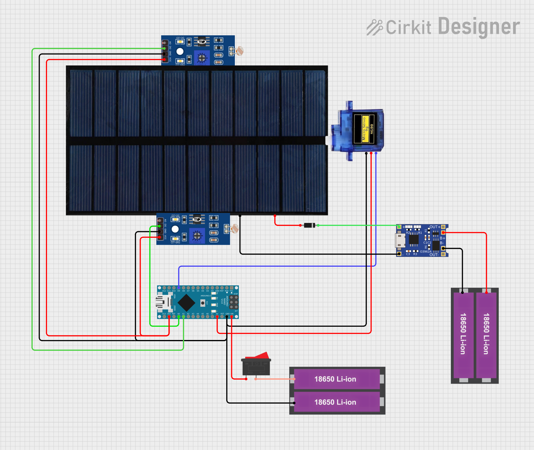
Circuit Documentation
Summary
This circuit is designed to integrate various components including an Arduino Nano, LDRs (Light Dependent Resistors), a Micro Servo, a TP4056 battery charger, a solar cell, a rocker switch, and 18650 Li-ion batteries. The circuit is intended to perform light sensing and control a servo motor based on the light intensity. The power management is handled by the TP4056 module, which charges the batteries using a solar cell.
Component List
LDR (Light Dependent Resistor)
- Pins: A0, D0, GND, VCC
- Description: A resistor whose resistance decreases with increasing incident light intensity.
- Purpose: To sense the ambient light levels.
TP4056
- Pins: OUT-, B-, B+, OUT+, IN-, IN+
- Description: A lithium battery charger module.
- Purpose: To charge the 18650 Li-ion batteries using the solar cell.
Solar Cell
- Pins: +, -
- Description: A device that converts light energy into electrical energy.
- Purpose: To provide power to the TP4056 module for charging the batteries.
Rocker Switch
- Pins: 1, 2
- Description: A switch that can toggle between two states.
- Purpose: To control the power supply to the Arduino Nano.
18650 Li-ion Battery x 2
- Pins: +, -
- Description: Rechargeable lithium-ion batteries.
- Purpose: To store electrical energy and provide power to the circuit.
Arduino Nano
- Pins: D1/TX, D0/RX, RESET, GND, D2, D3, D4, D5, D6, D7, D8, D9, D10, D11/MOSI, D12/MISO, VIN, 5V, A7, A6, A5, A4, A3, A2, A1, A0, AREF, 3V3, D13/SCK
- Description: A small, complete, and breadboard-friendly microcontroller board.
- Purpose: To control the servo motor and process the input from the LDRs.
Micro Servo 9G
- Pins: GND, +5V, PWM
- Description: A small servo motor.
- Purpose: To perform mechanical movements based on the Arduino Nano's control signals.
Diode
- Pins: cathode, anode
- Description: A semiconductor device that allows current to flow in one direction only.
- Purpose: To prevent reverse current flow from the TP4056 to the solar cell.
Wiring Details
LDR (Light Dependent Resistor)
- GND: Connected to GND of the Arduino Nano, Micro Servo, and another LDR.
- D0: Connected to A1 of the Arduino Nano.
- VCC: Connected to VCC of another LDR and 3V3 of the Arduino Nano.
TP4056
- B-: Connected to the negative terminal of one 18650 Li-ion Battery.
- B+: Connected to the positive terminal of one 18650 Li-ion Battery.
- IN-: Connected to the negative terminal of the Solar Cell.
- IN+: Connected to the cathode of the Diode.
- OUT-: Not connected in this circuit.
- OUT+: Not connected in this circuit.
Solar Cell
- -: Connected to IN- of the TP4056.
- +: Connected to the anode of the Diode.
Rocker Switch
- 1: Connected to VIN of the Arduino Nano.
- 2: Connected to the positive terminal of one 18650 Li-ion Battery.
18650 Li-ion Battery x 2
- -: Connected to GND of the Arduino Nano, Micro Servo, and LDRs.
- +: Connected to the B+ of the TP4056 and pin 2 of the Rocker Switch.
Arduino Nano
- VIN: Connected to pin 1 of the Rocker Switch.
- GND: Connected to GND of the Micro Servo, LDRs, and 18650 Li-ion Battery.
- 5V: Connected to +5V of the Micro Servo.
- 3V3: Connected to VCC of the LDRs.
- A0: Connected to D0 of one LDR.
- A1: Connected to D0 of another LDR.
- D9: Connected to PWM of the Micro Servo.
Micro Servo 9G
- GND: Connected to GND of the Arduino Nano and LDRs.
- +5V: Connected to 5V of the Arduino Nano.
- PWM: Connected to D9 of the Arduino Nano.
Diode
- cathode: Connected to IN+ of the TP4056.
- anode: Connected to the positive terminal of the Solar Cell.
Documented Code
Arduino Nano Code (sketch.ino)
void setup() {
  // put your setup code here, to run once:

}

void loop() {
  // put your main code here, to run repeatedly:

}
Additional Documentation (documentation.txt)
This documentation provides a comprehensive overview of the circuit, including a summary, detailed component list, wiring details, and the code used in the Arduino Nano.