Cirkit Designer
Your all-in-one circuit design IDE
Home /
Project Documentation
Logic Gate Experimentation Board with DIP Switch Control and LED Indicators

Circuit Documentation
Summary of the Circuit
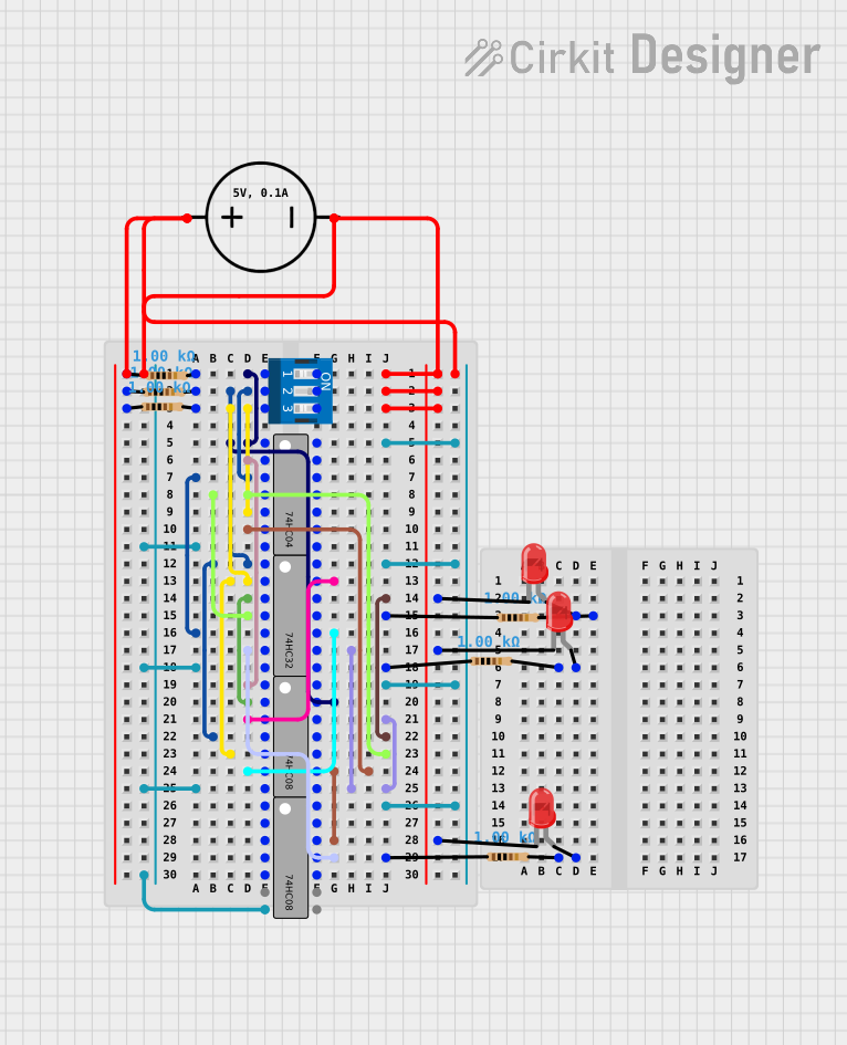
This circuit appears to be a digital logic circuit that utilizes a combination of logic gates, DIP switches, resistors, and LEDs. The DIP switches likely serve as input devices to control the logic flow through the gates, which then drive the LEDs based on the logic conditions. The resistors are used to limit current to the LEDs, and the DC power source provides the necessary voltage to the circuit. There are no microcontrollers or embedded code involved in this circuit.
Component List
DIP Switch 3 Position
- Description: A three-position dual in-line package (DIP) switch used for setting logic levels manually.
- Pins: 6 (1, 2, 3, 4, 5, 6)
74HC04
- Description: Hex inverter logic gate, which inverts the input signal.
- Pins: 14 (A1, Y1, A2, Y2, A3, Y3, GND, VCC, A6, Y6, A5, Y5, A4, Y4)
74HC32
- Description: Quad 2-input OR gate, which outputs high if any input is high.
- Pins: 14 (A1, B1, Y1, A2, B2, Y2, GND, VCC, B4, A4, Y4, B3, A3, Y3)
74HC08
- Description: Quad 2-input AND gate, which outputs high only if both inputs are high.
- Pins: 14 (A1, B1, Y1, A2, B2, Y2, GND, VCC, B4, A4, Y4, B3, A3, Y3)
Resistor (1k Ohms)
- Description: A resistor with a resistance of 1000 Ohms, used to limit current.
- Pins: 2 (pin1, pin2)
DC Power Source
- Description: Provides the voltage and ground reference for the circuit.
- Pins: 2 (Ground, Positive)
LED: Two Pin (red)
- Description: A red light-emitting diode used as an output indicator.
- Pins: 2 (cathode, anode)
Wiring Details
DIP Switch 3 Position
- Pin 1 connected to Resistor (pin2), 74HC04 (A1), and 74HC08 (B4)
- Pin 2 connected to Resistor (pin2), 74HC32 (A1, B2), and 74HC08 (A2)
- Pin 3 connected to Resistor (pin2), 74HC32 (B1), and 74HC08 (B2)
- Pin 4 connected to ground net
- Pin 5 connected to ground net
- Pin 6 connected to ground net
74HC04
- Pin A1 connected to DIP Switch (1) and 74HC08 (B4)
- Pin Y1 connected to 74HC08 (A1)
- Pin A2 connected to 74HC32 (A2) and 74HC08 (A2)
- Pin Y2 connected to 74HC32 (A2) and 74HC08 (B3)
- Pin A3 connected to 74HC08 (B2)
- Pin Y3 connected to 74HC08 (A3, A4)
- Pin GND connected to ground net
- Pin VCC connected to power net
74HC32
- Pin A1 connected to DIP Switch (2) and 74HC08 (A2)
- Pin B1 connected to DIP Switch (3) and 74HC08 (B2)
- Pin Y1 connected to 74HC08 (B1)
- Pin A2 connected to 74HC04 (Y2) and 74HC08 (B3)
- Pin B2 connected to 74HC32 (A1)
- Pin Y2 connected to 74HC08 (Y4) and Resistor (pin1)
- Pin A3 connected to 74HC08 (A4)
- Pin B3 connected to 74HC08 (Y2)
- Pin A4 connected to 74HC08 (Y4)
- Pin B4 connected to 74HC08 (Y1)
- Pin Y3 connected to Resistor (pin1)
- Pin Y4 connected to Resistor (pin1)
- Pin GND connected to ground net
- Pin VCC connected to power net
74HC08
- Pin A1 connected to 74HC04 (Y1)
- Pin B1 connected to 74HC32 (Y1)
- Pin Y1 connected to 74HC32 (B4)
- Pin A2 connected to 74HC32 (A1, B2)
- Pin B2 connected to 74HC04 (A3)
- Pin Y2 connected to 74HC32 (B3)
- Pin A3 connected to 74HC04 (Y3)
- Pin B3 connected to 74HC04 (Y2)
- Pin Y3 connected to 74HC08 (A4)
- Pin A4 connected to 74HC32 (A3)
- Pin B4 connected to DIP Switch (1)
- Pin Y4 connected to 74HC32 (A4)
- Pin GND connected to ground net
- Pin VCC connected to power net
Resistor (1k Ohms)
- Pin1 connected to power net
- Pin2 connected to various components (DIP Switch, 74HC04, 74HC32, LEDs)
DC Power Source
- Ground connected to ground net
- Positive connected to power net
LED: Two Pin (red)
- Cathode connected to ground net
- Anode connected to Resistor (pin2)
Documented Code
There is no embedded code provided for this circuit as it does not contain any programmable components such as microcontrollers. The circuit operates solely based on the logic provided by the digital logic ICs and the state of the DIP switches.