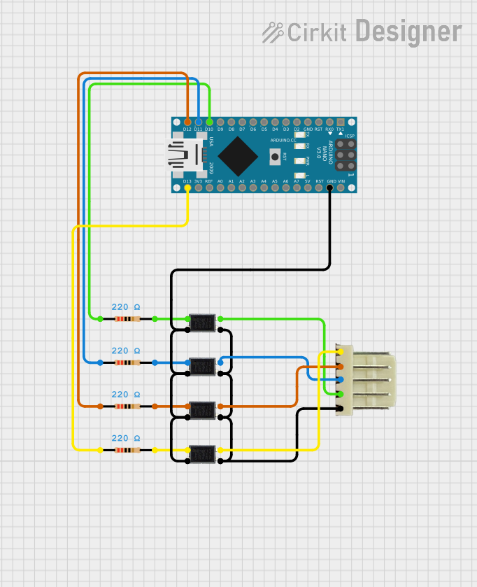
Arduino Nano Controlled Octocoupler Interface for Signal Isolation

Circuit Documentation
Summary of the Circuit
This circuit appears to be designed to interface an Arduino Nano with multiple octocouplers and external devices through a 5-pin relimate connector. The octocouplers are used to provide electrical isolation between the Arduino Nano and the external devices connected via the relimate connector. Each octocoupler is paired with a resistor, likely for current limiting purposes. The common cathodes of the octocouplers are connected to the ground (GND) of the Arduino, while the emitters are connected to various signal lines on the relimate connector. The anodes of the octocouplers are connected through resistors to different digital pins on the Arduino Nano, which suggests that these pins are used to drive the octocouplers.
Component List
Octocoupler
- Description: An electronic component that transfers electrical signals between two isolated circuits by using light.
- Pins: Anode, Cathode, Collector, Emitter
Resistor
- Description: A passive two-terminal electrical component that implements electrical resistance as a circuit element.
- Value: 220 Ohms
5-pin Relimate Connector
- Description: A connector used for making quick and easy connections between boards.
- Pins: VCC, GND, SDA, SCL, ADDR
Arduino Nano
- Description: A small, complete, and breadboard-friendly board based on the ATmega328 (Arduino Nano 3.x).
- Pins: D1/TX, D0/RX, RESET, GND, D2, D3, D4, D5, D6, D7, D8, D9, D10, D11/MOSI, D12/MISO, VIN, 5V, A7, A6, A5, A4, A3, A2, A1, A0, AREF, 3V3, D13/SCK
Wiring Details
Octocoupler Wiring
- Anode: Connected to a digital pin on the Arduino Nano through a 220 Ohm resistor.
- Cathode: Commonly connected to the GND pin on the Arduino Nano.
- Collector: Connected to a signal line on the 5-pin relimate connector (SDA, SCL, VCC, or GND).
- Emitter: Commonly connected to the ADDR signal line on the 5-pin relimate connector.
Resistor Wiring
- Pin1: Connected to a digital pin on the Arduino Nano (D10, D11/MOSI, D13/SCK, or D12/MISO).
- Pin2: Connected to the anode of an octocoupler.
5-pin Relimate Connector Wiring
- VCC: Connected to the collector of an octocoupler.
- GND: Connected to the collector of an octocoupler.
- SDA: Connected to the collector of an octocoupler.
- SCL: Connected to the collector of an octocoupler.
- ADDR: Commonly connected to the emitters of the octocouplers.
Arduino Nano Wiring
- Digital Pins (D10, D11/MOSI, D13/SCK, D12/MISO): Each connected to a 220 Ohm resistor which is then connected to the anode of an octocoupler.
- GND: Commonly connected to the cathodes of the octocouplers.
Documented Code
Arduino Nano Code (sketch.ino)
void setup() {
  // put your setup code here, to run once:

}

void loop() {
  // put your main code here, to run repeatedly:

}
Additional Notes (documentation.txt)
No additional code or notes provided.