Arduino UNO and Nano Controlled GPS Tracking System with Relay and Servo Integration
Circuit Documentation
Summary
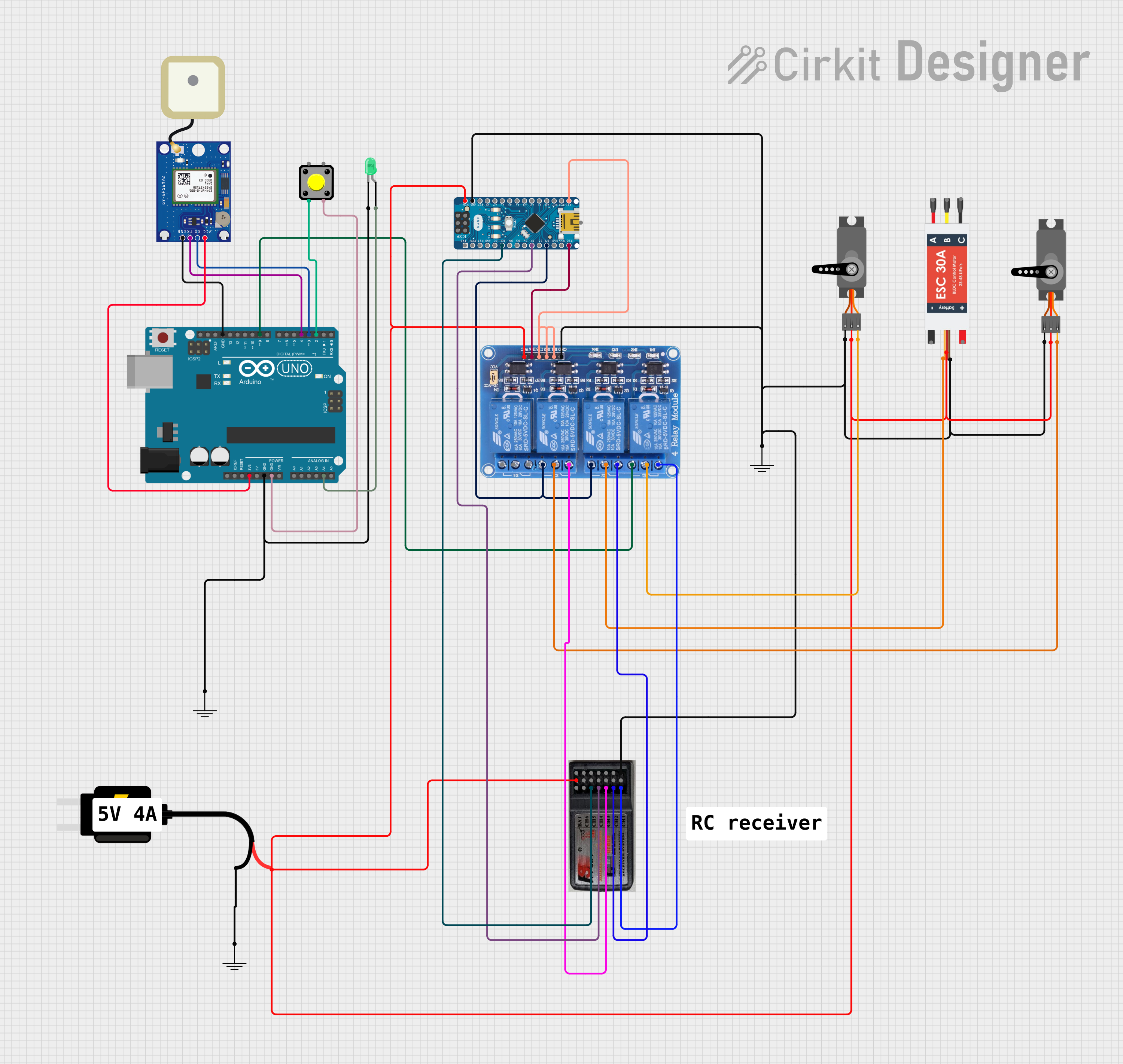
This document provides a detailed overview of a circuit that includes a variety of components such as microcontrollers (Arduino UNO and Arduino Nano), a GPS module (GPS NEO-6M V2), a relay module (Relay 4 Channel 5v), input devices (Pushbutton), output devices (LED, Servo, Electronic Speed Controller), and power sources (DC Source 5V). The circuit is designed to interface with a GPS module, control relays, and manage input from a pushbutton and RC receiver. It also includes code for the Arduino UNO and Arduino Nano microcontrollers to control the circuit's behavior.
Component List
Microcontrollers
- Arduino UNO: A microcontroller board based on the ATmega328P, featuring digital and analog I/O pins.
- Arduino Nano: A small, complete, and breadboard-friendly board based on the ATmega328P, similar to the UNO but in a smaller form factor.
Modules
- GPS NEO-6M V2: A GPS module that provides location data.
- Relay 4 Channel 5v: A 4-channel relay module capable of controlling high power loads with Arduino boards.
Input Devices
- Pushbutton: A simple switch mechanism for controlling some aspect of a machine or a process.
Output Devices
- LED: Two Pin (green): A basic green LED for indication purposes.
- Servo: A rotary actuator that allows for precise control of angular position.
- Electronic Speed Controller (ESC): An electronic circuit with the purpose to vary an electric motor's speed, its direction, and possibly also to act as a dynamic brake.
Power Sources
- DC Source 5V: A power supply module that provides 5V DC power.
Others
- RC Receiver 6 channels: A radio control receiver that receives control signals and outputs PWM signals.
- GND: A common ground reference point in an electrical circuit.
Wiring Details
Arduino UNO
- 3.3V connected to GPS NEO-6M V2 VCC.
- GND connected to LED cathode, Pushbutton Pin 3, and GPS NEO-6M V2 GND.
- A4 connected to LED anode.
- D9 connected to Relay 4 Channel 5v NO1.
- D4 connected to GPS NEO-6M V2 TX.
- D3 connected to GPS NEO-6M V2 RX.
- D2 connected to Pushbutton Pin 2.
Arduino Nano
- GND connected to RC Receiver 6 channels GND, Servo GND, ESC GND out, and Relay 4 Channel 5v GND.
- D13/SCK connected to Relay 4 Channel 5v IN1, IN2, IN3.
- D12/MISO connected to Relay 4 Channel 5v IN4.
- VIN connected to RC Receiver 6 channels VCC.
- D9 connected to Relay 4 Channel 5v NO2, NO3.
- D3 connected to RC Receiver 6 channels CH5.
- D7 connected to RC Receiver 6 channels CH4.
GPS NEO-6M V2
- VCC connected to Arduino UNO 3.3V.
- GND connected to Arduino UNO GND.
- TX connected to Arduino UNO D4.
- RX connected to Arduino UNO D3.
Relay 4 Channel 5v
- GND connected to Arduino Nano GND.
- IN1, IN2, IN3 connected to Arduino Nano D13/SCK.
- IN4 connected to Arduino Nano D12/MISO.
- VCC connected to DC Source 5V VCC.
- COM1 connected to Servo PWM.
- COM2 connected to ESC Signal.
- COM3 connected to Servo PWM.
- NO1 connected to Arduino UNO D9.
- NO2, NO3 connected to Arduino Nano D9.
- NC1 connected to RC Receiver 6 channels CH1.
- NC2 connected to RC Receiver 6 channels CH2.
- NC3 connected to RC Receiver 6 channels CH3.
LED: Two Pin (green)
- Cathode connected to Arduino UNO GND.
- Anode connected to Arduino UNO A4.
Pushbutton
- Pin 2 connected to Arduino UNO D2.
- Pin 3 connected to Arduino UNO GND.
Servo
- GND connected to Arduino Nano GND.
- VCC connected to DC Source 5V VCC.
- PWM connected to Relay 4 Channel 5v COM1 and COM3.
Electronic Speed Controller (ESC)
- GND out connected to Arduino Nano GND.
- 5v out connected to DC Source 5V VCC.
- Signal connected to Relay 4 Channel 5v COM2.
RC Receiver 6 channels
- GND connected to Arduino Nano GND.
- VCC connected to Arduino Nano VIN.
- CH1 connected to Relay 4 Channel 5v NC1.
- CH2 connected to Relay 4 Channel 5v NC2.
- CH3 connected to Relay 4 Channel 5v NC3.
- CH4 connected to Arduino Nano D7.
- CH5 connected to Arduino Nano D3.
DC Source 5V
- VCC connected to RC Receiver 6 channels VCC, Servo VCC, ESC 5v out, Relay 4 Channel 5v VCC.
- GND connected to a common ground reference.
Documented Code
Arduino UNO Code (sketch.ino)
void setup() {
  // put your setup code here, to run once:

}

void loop() {
  // put your main code here, to run repeatedly:

}
Arduino Nano Code (sketch.ino)
void setup() {
  // put your setup code here, to run once:

}

void loop() {
  // put your main code here, to run repeatedly:

}
Note: The provided code for both Arduino UNO and Arduino Nano is a template with empty setup and loop functions. The actual functionality needs to be implemented according to the requirements of the circuit's operation.