
ESP32-Based Smart Greenhouse Monitoring System with Wi-Fi and Firebase Integration
View and Edit Project In Cirkit Designer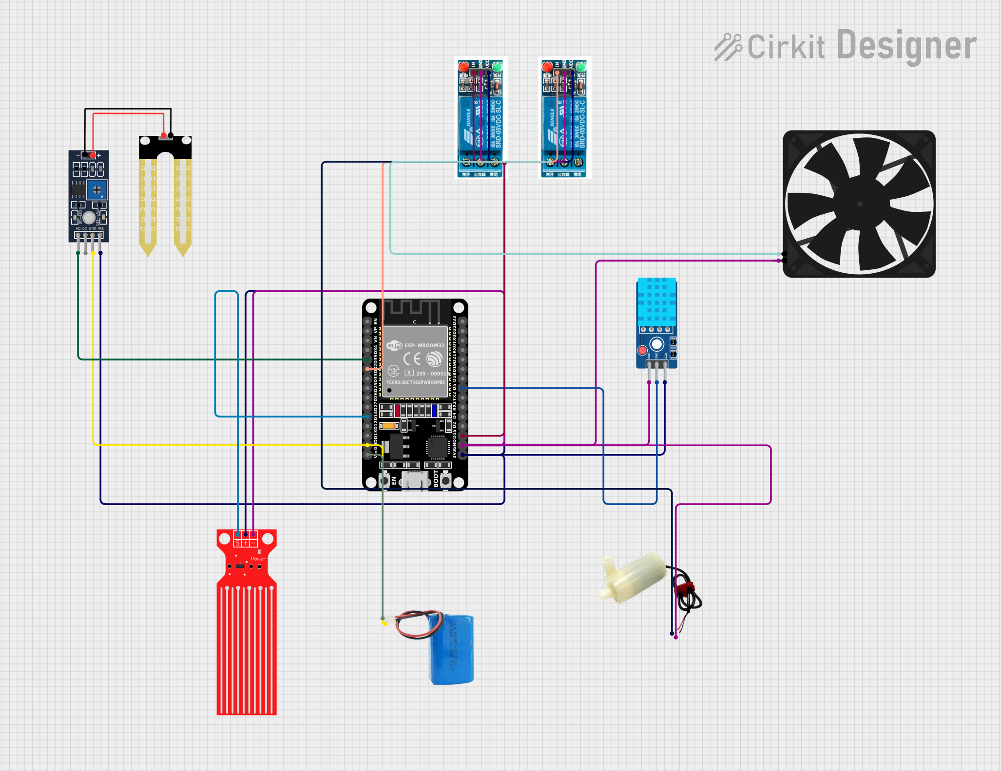
Smart Greenhouse Monitoring System Circuit Documentation
Summary
The Smart Greenhouse Monitoring System is designed to monitor and control environmental conditions within a greenhouse. It utilizes an ESP32 microcontroller to interface with various sensors and actuators, including a DHT11 temperature and humidity sensor, a YL-69 soil moisture sensor, a water level sensor, relays for controlling a water pump and a fan, and a 5V power supply. The system is capable of reading environmental data and adjusting the conditions by controlling the water pump and fan based on predefined thresholds. The ESP32 is also connected to Blynk and Firebase for remote monitoring and data logging.
Component List
DHT11 Sensor V2
- Description: A temperature and humidity sensor that provides digital output.
- Pins: GND, DAT, VCC
Humidity YL-69
- Description: A soil moisture sensor that provides both analog and digital outputs.
- Pins: A0, D0, GND, VCC
5V Mini Water Pump
- Description: A small pump for water circulation, controlled by a relay.
- Pins: Positive pin, Negative pin
Fan
- Description: A 5V fan used for air circulation within the greenhouse.
- Pins: GND, 5V
5V Battery
- Description: A power source for the system.
- Pins: Positive, Negative
ESP32 (30 Pin)
- Description: A microcontroller with Wi-Fi capabilities for controlling and monitoring the system.
- Pins: EN, VP, VN, D34, D35, D32, D33, D25, D26, D27, D14, D12, D13, GND, Vin, D23, D22, TX0, RX0, D21, D19, D18, D5, TX2, RX2, D4, D2, D15, 3V3
5V Relay
- Description: An electromechanical switch used for controlling high power devices like the water pump and fan.
- Pins: Normally Open, Common terminal, Normally Closed, In, GND, VCC
Water Level Sensor
- Description: A sensor that detects the presence of water.
- Pins: SIG, VCC, GND
Wiring Details
DHT11 Sensor V2
- DAT: Connected to ESP32 pin D5
- GND: Connected to common ground
- VCC: Connected to ESP32 pin 3V3
Humidity YL-69
- A0: Connected to ESP32 pin D35
- D0: Not connected
- GND: Connected to common ground
- VCC: Connected to ESP32 pin 3V3
5V Mini Water Pump
- Positive Pin: Connected to the Normally Open pin of one 5V relay
- Negative Pin: Connected to common ground
Fan
- GND: Connected to common ground
- 5V: Connected to the Normally Open pin of another 5V relay
5V Battery
- Positive: Connected to ESP32 pin Vin
- Negative: Connected to common ground
ESP32 (30 Pin)
- D35: Connected to Humidity YL-69 pin A0
- D32: Connected to one 5V relay pin In (for fan control)
- D14: Connected to Water Level Sensor pin SIG
- GND: Connected to common ground
- Vin: Connected to 5V battery positive
- D5: Connected to DHT11 Sensor V2 pin DAT
- D15: Connected to another 5V relay pin In (for water pump control)
- 3V3: Connected to VCC pins of DHT11 Sensor V2, Humidity YL-69, both 5V relays, and Water Level Sensor
5V Relay (for water pump)
- Normally Open: Connected to 5V Mini Water Pump positive pin
- Common Terminal: Not connected
- Normally Closed: Not connected
- In: Connected to ESP32 pin D15
- GND: Connected to common ground
- VCC: Connected to ESP32 pin 3V3
5V Relay (for fan)
- Normally Open: Connected to Fan pin 5V
- Common Terminal: Not connected
- Normally Closed: Not connected
- In: Connected to ESP32 pin D32
- GND: Connected to common ground
- VCC: Connected to ESP32 pin 3V3
Water Level Sensor
- SIG: Connected to ESP32 pin D14
- VCC: Connected to ESP32 pin 3V3
- GND: Connected to common ground
Documented Code
The code for the ESP32 microcontroller is written in C++ and is designed to be compiled and uploaded using the Arduino IDE. The code includes libraries for the DHT sensor, Blynk, WiFi, and Firebase to facilitate sensor readings, control actuators, and communicate with remote services for data logging and monitoring.
// Include necessary libraries
#include <DHT.h>
#include <BlynkSimpleEsp32.h>
#include <WiFi.h>
#include <FirebaseESP32.h>

// Define constants for Blynk and Firebase
#define BLYNK_TEMPLATE_ID "TMPL6o0woVv00"
#define BLYNK_TEMPLATE_NAME "Smart Green House Monitoring System"
#define BLYNK_AUTH_TOKEN "AToqA3zayEOBl25VyE-lmPJIqbo1qABA"
#define FIREBASE_HOST "smartgreenhouseprojectgroup05-default-rtdb.asia-southeast1.firebasedatabase.app"
#define FIREBASE_AUTH "ekbPCRO9qRZ8GBJI72HzHPoVKRRaf4E9i4IGVwwp"

// Wi-Fi credentials
const char* ssid = "Maleesha";
const char* password = "03022001";

// Pin definitions
#define DHTPIN 5
#define DHTTYPE DHT11
#define SOIL_MOISTURE_PIN 35
#define RELAY_PIN 15
#define FAN_PIN 32

// Create sensor and control objects
DHT dht(DHTPIN, DHTTYPE);

// Variables for sensor readings and control states
int soilMoistureValue = 0;
const int soilMoistureThreshold = 2500;
String waterPumpState = "OFF";
String fanState = "OFF";
const float fanTemperatureThreshold = 27.0;

// Firebase and Blynk data objects
FirebaseData firebaseData;
FirebaseConfig config;
FirebaseAuth auth;

// Setup function to initialize components
void setup() {
    Serial.begin(115200);
    pinMode(SOIL_MOISTURE_PIN, INPUT);
    pinMode(RELAY_PIN, OUTPUT);
    pinMode(FAN_PIN, OUTPUT);
    digitalWrite(RELAY_PIN, HIGH);
    digitalWrite(FAN_PIN, HIGH);
    dht.begin();
    Blynk.begin(BLYNK_AUTH_TOKEN, ssid, password);
    config.host = FIREBASE_HOST;
    config.signer.tokens.legacy_token = FIREBASE_AUTH;
    Firebase.begin(&config, &auth);
    Firebase.reconnectWiFi(true);
    Serial.println("System Initialized - Water pump OFF, Fan OFF");
}

// Main loop function
void loop() {
    // Read sensors and control actuators
    // ... (code continues with sensor reading, control logic, and communication)
}

// ... (rest of the code)
The code is structured with a setup function to initialize the system and a loop function that continuously reads sensor data, controls the actuators, and communicates with Blynk and Firebase. The ESP32 reads the soil moisture level and controls the water pump based on the threshold. It also reads temperature and humidity from the DHT11 sensor and controls the fan based on the temperature threshold. Sensor data is sent to Blynk for real-time monitoring and to Firebase for data logging.