
Arduino UNO-Based Smart Home Automation System with Bluetooth Control
View and Edit Project In Cirkit Designer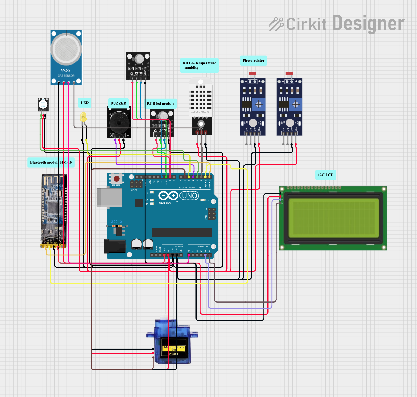
Circuit Documentation
Summary
This circuit is designed to control various components based on sensor inputs using an Arduino UNO. The components include a photoresistor, servo motor, LED, RGB LED, buzzer, DHT22 sensor, MQ2 sensor, LCD display, and a Bluetooth module. The Arduino UNO reads sensor data and controls the output devices accordingly. The circuit also allows for Bluetooth control via a mobile application.
Component List
Arduino UNO
- Description: Microcontroller board based on the ATmega328P.
- Pins: UNUSED, IOREF, Reset, 3.3V, 5V, GND, Vin, A0, A1, A2, A3, A4, A5, SCL, SDA, AREF, D13, D12, D11, D10, D9, D8, D7, D6, D5, D4, D3, D2, D1, D0
Resistor
- Description: 200 Ohms resistor.
- Pins: pin1, pin2
Passive Buzzer
- Description: Buzzer that produces sound when a voltage is applied.
- Pins: S output signal, +VCC, GND
RGB LED Module
- Description: RGB LED module with separate control for red, green, and blue LEDs.
- Pins: +VCC Red, +VCC Green, +VCC Blue, GND
DHT22
- Description: Temperature and humidity sensor.
- Pins: +, Out, -
Photoresistor (LDR) Sensor
- Description: Light-dependent resistor sensor.
- Pins: VCC, GND, DO, AO
LED: Two Pin (yellow)
- Description: Yellow LED.
- Pins: cathode, anode
Bluetooth Module HM-10
- Description: Bluetooth module for wireless communication.
- Pins: BRK, RX, TX, GND, VCC, State
KY-012
- Description: Active buzzer module.
- Pins: signal, 5v, GND
MQ-2
- Description: Gas sensor for detecting LPG, i-butane, propane, methane, alcohol, hydrogen, and smoke.
- Pins: GND, VCC, ANALOG, Digital
Micro Servo 9G
- Description: Small servo motor.
- Pins: GND, +5V, PWM
LCD 20x4 I2C
- Description: 20x4 character LCD display with I2C interface.
- Pins: GND, 5v, SCA, SCL
Wiring Details
Arduino UNO
- 3.3V: Connected to VCC of Bluetooth module HM-10
- 5V: Connected to +5V of Micro servo 9G, + of DHT22, VCC of Photoresistor (LDR) Sensor, 5v of LCD 20x4 I2C, +VCC of Passive Buzzer, VCC of MQ-2, 5v of KY-012
- GND: Connected to GND of Bluetooth module HM-10, GND of Micro servo 9G, - of DHT22, GND of Photoresistor (LDR) Sensor, GND of LCD 20x4 I2C, GND of Passive Buzzer, GND of MQ-2, GND of KY-012, cathode of LED: Two Pin (yellow), GND of RGB LED module
- A0: Connected to ANALOG of MQ-2
- A4: Connected to SCA of LCD 20x4 I2C
- A5: Connected to SCL of LCD 20x4 I2C
- D11: Connected to +VCC Blue of RGB LED module
- D10: Connected to +VCC Green of RGB LED module
- D9: Connected to +VCC Red of RGB LED module
- D6: Connected to PWM of Micro servo 9G
- D5: Connected to anode of LED: Two Pin (yellow)
- D4: Connected to S output signal of Passive Buzzer
- D3: Connected to signal of KY-012
- D2: Connected to Out of DHT22, Digital of MQ-2
- D1: Connected to TX of Bluetooth module HM-10
- D0: Connected to RX of Bluetooth module HM-10
Resistor
- pin1: Not connected
- pin2: Not connected
Passive Buzzer
- S output signal: Connected to D4 of Arduino UNO
- +VCC: Connected to 5V of Arduino UNO
- GND: Connected to GND of Arduino UNO
RGB LED Module
- +VCC Red: Connected to D9 of Arduino UNO
- +VCC Green: Connected to D10 of Arduino UNO
- +VCC Blue: Connected to D11 of Arduino UNO
- GND: Connected to GND of Arduino UNO
DHT22
- +: Connected to 5V of Arduino UNO
- Out: Connected to D2 of Arduino UNO
- -: Connected to GND of Arduino UNO
Photoresistor (LDR) Sensor
- VCC: Connected to 5V of Arduino UNO
- GND: Connected to GND of Arduino UNO
- DO: Not connected
- AO: Not connected
LED: Two Pin (yellow)
- cathode: Connected to GND of Arduino UNO
- anode: Connected to D5 of Arduino UNO
Bluetooth Module HM-10
- BRK: Not connected
- RX: Connected to D0 of Arduino UNO
- TX: Connected to D1 of Arduino UNO
- GND: Connected to GND of Arduino UNO
- VCC: Connected to 3.3V of Arduino UNO
- State: Not connected
KY-012
- signal: Connected to D3 of Arduino UNO
- 5v: Connected to 5V of Arduino UNO
- GND: Connected to GND of Arduino UNO
MQ-2
- GND: Connected to GND of Arduino UNO
- VCC: Connected to 5V of Arduino UNO
- ANALOG: Connected to A0 of Arduino UNO
- Digital: Connected to D2 of Arduino UNO
Micro Servo 9G
- GND: Connected to GND of Arduino UNO
- +5V: Connected to 5V of Arduino UNO
- PWM: Connected to D6 of Arduino UNO
LCD 20x4 I2C
- GND: Connected to GND of Arduino UNO
- 5v: Connected to 5V of Arduino UNO
- SCA: Connected to A4 of Arduino UNO
- SCL: Connected to A5 of Arduino UNO
Code Documentation
/*
 * This Arduino sketch controls various components based on sensor inputs.
 * - A photoresistor controls a servo motor and an LED.
 * - An RGB LED and buzzer are controlled by a DHT22 sensor and an MQ2 sensor.
 * - An LCD displays temperature and humidity levels.
 * - A Bluetooth module allows control via a mobile application.
 */

#include <Servo.h>
#include <Wire.h>
#include <LiquidCrystal_I2C.h>
#include <DHT.h>

// Pin definitions
#define PHOTORESISTOR_SERVO A0
#define PHOTORESISTOR_LED A1
#define SERVO_PIN 6
#define LED_PIN 5
#define DHT_PIN 2
#define MQ2_PIN 3
#define BUZZER_PIN 4
#define RGB_RED_PIN 9
#define RGB_GREEN_PIN 10
#define RGB_BLUE_PIN 11
#define BLUETOOTH_RX 0
#define BLUETOOTH_TX 1

// Constants
#define DHT_TYPE DHT22
#define TEMP_THRESHOLD 25

// Objects
Servo myServo;
LiquidCrystal_I2C lcd(0x27, 20, 4);
DHT dht(DHT_PIN, DHT_TYPE);

void setup() {
  // Initialize serial communication
  Serial.begin(9600);
  // Initialize components
  myServo.attach(SERVO_PIN);
  pinMode(LED_PIN, OUTPUT);
  pinMode(BUZZER_PIN, OUTPUT);
  pinMode(RGB_RED_PIN, OUTPUT);
  pinMode(RGB_GREEN_PIN, OUTPUT);
  pinMode(RGB_BLUE_PIN, OUTPUT);
  lcd.begin();
  lcd.backlight();
  dht.begin();
}

void loop() {
  // Read photoresistor values
  int lightLevelServo = analogRead(PHOTORESISTOR_SERVO);
  int lightLevelLED = analogRead(PHOTORESISTOR_LED);

  // Control servo based on light level
  if (lightLevelServo > 512) {
    myServo.write(180);
  } else {
    myServo.write(0);
  }

  // Control LED based on light level
  if (lightLevelLED > 512) {
    digitalWrite(LED_PIN, LOW);
  } else {
    digitalWrite(LED_PIN, HIGH);
  }

  // Read DHT22 sensor values