555 Timer-Based Audible Alert System with Visual Indicator
Circuit Documentation
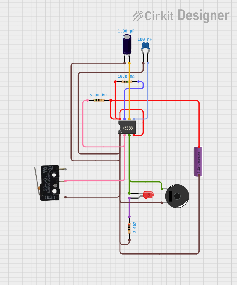
Summary of the Circuit
This circuit appears to be a timer or pulse generator using a 555 Timer IC, which is a common component for such applications. The circuit is powered by a 3.7V battery and includes a micro switch to trigger the operation. The output of the 555 Timer IC is connected to both an LED and a piezo buzzer, indicating that the circuit provides both visual and audible indications when activated. The circuit also includes resistors and capacitors that are likely used to set the timing intervals and stabilize the operation of the 555 Timer IC.
Component List
Micro Switch
- Description: A switch that toggles between an open and closed state when actuated.
- Pins: COM (Common), NO (Normally Open), NC (Normally Closed)
LED: Two Pin (red)
- Description: A red light-emitting diode that illuminates when forward-biased.
- Pins: cathode, anode
Resistor
- Description: A passive two-terminal electrical component that implements electrical resistance as a circuit element.
- Properties: Various resistance values (200 Ohms, 10 MΩ, 5 kΩ)
555 Timer IC
- Description: An integrated circuit used in a variety of timer, pulse generation, and oscillator applications.
- Pins: VCC+, Dis, Th, CV, Rst, Out, Trig, GND
Ceramic Capacitor
- Description: A fixed-value capacitor where the ceramic material acts as the dielectric.
- Properties: Capacitance of 0.1 µF
Electrolytic Capacitor
- Description: A polarized capacitor with an anode (+) and cathode (-) that has a larger capacitance per unit volume than other types of capacitors.
- Properties: Capacitance of 1 µF
3.7v Battery
- Description: A power source for the circuit.
- Pins: + (positive), - (negative)
Piezo Buzzer
- Description: An electronic device that emits sound when an electrical signal is applied.
- Pins: pin 1, pin 2
Wiring Details
Micro Switch
- COM is connected to the common ground net.
- NO is connected to the trigger (Trig) pin of the 555 Timer IC.
LED: Two Pin (red)
- cathode is connected to the output (Out) pin of the 555 Timer IC.
- anode is connected to one end of a 200 Ohm resistor.
Resistor (200 Ohms)
- One end is connected to the anode of the LED.
- The other end is connected to the positive supply voltage.
Resistor (10 MΩ)
- One end is connected to the positive supply voltage.
- The other end is connected to the discharge (Dis) pin of the 555 Timer IC.
Resistor (5 kΩ)
- One end is connected to the positive supply voltage.
- The other end is connected to the VCC+ and reset (Rst) pins of the 555 Timer IC.
555 Timer IC
- VCC+ is connected to the positive supply voltage through a 5 kΩ resistor.
- Dis is connected to a 10 MΩ resistor.
- Th is connected to the positive side of an electrolytic capacitor.
- CV is connected to one end of a ceramic capacitor.
- Rst is connected to the positive supply voltage through a 5 kΩ resistor.
- Out is connected to the cathode of the LED and pin 1 of the Piezo Buzzer.
- Trig is connected to the normally open (NO) terminal of the Micro Switch.
- GND is connected to the common ground net.
Ceramic Capacitor (0.1 µF)
- One end is connected to the control voltage (CV) pin of the 555 Timer IC.
- The other end is connected to the common ground net.
Electrolytic Capacitor (1 µF)
- The positive side is connected to the threshold (Th) pin of the 555 Timer IC.
- The negative side is connected to the common ground net.
3.7v Battery
- The positive terminal is connected to the positive supply voltage net.
- The negative terminal is connected to the common ground net.
Piezo Buzzer
- pin 1 is connected to the output (Out) pin of the 555 Timer IC.
- pin 2 is connected to the common ground net.
Documented Code
There is no code provided for any microcontrollers in this circuit. The 555 Timer IC operates based on the analog components and connections provided. If there were any microcontrollers in the circuit, the code would be documented in this section.