Cirkit Designer
Your all-in-one circuit design IDE
Home /
Project Documentation
Arduino-Controlled Ultrasonic Sensor Array with DC Motor Actuation and Rocker Switch Power Control

Circuit Documentation
Summary
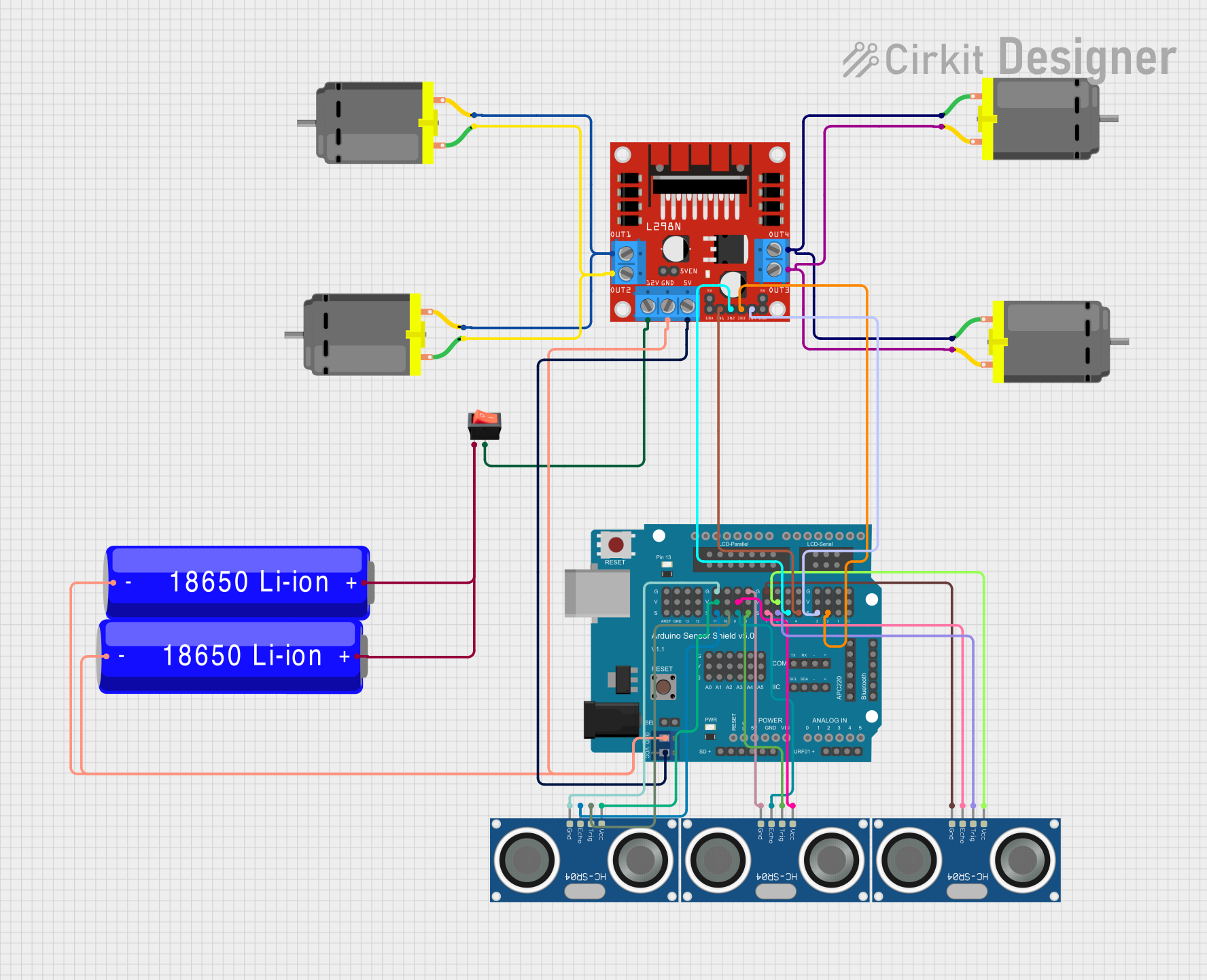
This circuit is designed to control multiple DC motors using an Arduino UNO microcontroller and an L298N DC motor driver. The circuit also includes multiple HC-SR04 Ultrasonic Sensors for distance measurement and a rocker switch to control the power supply. The power is provided by two 18650 Li-ion batteries. An Arduino Sensor Shield v5.0 is used to facilitate the wiring of sensors and the motor driver to the Arduino UNO.
Component List
Rocker Switch
- Description: A switch to control the power supply to the circuit.
- Pins: output, input
HC-SR04 Ultrasonic Sensor
- Description: Ultrasonic distance measuring sensor.
- Pins: VCC, TRIG, ECHO, GND
DC Motor
- Description: A motor that converts electrical energy into mechanical energy.
- Pins: pin 1, pin 2
18650 Li-ion Battery
- Description: A rechargeable battery that supplies power to the circuit.
- Pins: -, +
Arduino UNO
- Description: A microcontroller board based on the ATmega328P.
- Pins: UNUSED, IOREF, Reset, 3.3V, 5V, GND, Vin, A0-A5, SCL, SDA, AREF, D0-D13
Arduino Sensor Shield v5.0
- Description: An expansion board that allows for easy connection of sensors and other devices to the Arduino UNO.
- Pins: Multiple VCC, GND, Signal, and special function pins.
L298N DC Motor Driver
- Description: A module that allows for control of up to two DC motors.
- Pins: OUT1-OUT4, 12V, GND, 5V, ENA, ENB, IN1-IN4
Wiring Details
Rocker Switch
- Input: Connected to the positive terminal of the 18650 Li-ion Batteries.
- Output: Connected to the 12V input of the L298N DC motor driver.
HC-SR04 Ultrasonic Sensors
- VCC: Connected to the VCC pins on the Arduino Sensor Shield v5.0.
- TRIG: Connected to the digital signal pins (10-S, 8-S, 6-S) on the Arduino Sensor Shield v5.0.
- ECHO: Connected to the digital signal pins (11-S, 9-S, 7-S) on the Arduino Sensor Shield v5.0.
- GND: Connected to the GND pins on the Arduino Sensor Shield v5.0.
DC Motors
- Pin 1: Connected to OUT2 and OUT4 of the L298N DC motor driver.
- Pin 2: Connected to OUT1 and OUT3 of the L298N DC motor driver.
18650 Li-ion Batteries
- +: Connected to the input of the rocker switch.
- -: Connected to the GND of the Arduino Sensor Shield v5.0 and the L298N DC motor driver.
Arduino UNO
- Utilizes the Arduino Sensor Shield v5.0 for connections to sensors and the motor driver.
Arduino Sensor Shield v5.0
- VCC: Supplies power to the HC-SR04 Ultrasonic Sensors.
- GND: Common ground for the circuit.
- Signal Pins: Connect to TRIG and ECHO pins of the HC-SR04 Ultrasonic Sensors and IN1-IN4 of the L298N DC motor driver.
L298N DC Motor Driver
- 12V: Receives power from the rocker switch.
- 5V: Connected to the VCC on the Arduino Sensor Shield v5.0.
- GND: Common ground for the circuit.
- IN1-IN4: Controlled by the Arduino UNO through the Arduino Sensor Shield v5.0.
- OUT1-OUT4: Connected to the DC Motors.
Documented Code
Arduino UNO Code (sketch.ino)
void setup() {
  // put your setup code here, to run once:

}

void loop() {
  // put your main code here, to run repeatedly:

}
Note: The provided code is a template and does not contain any functional code to control the motors or read the sensors. It needs to be populated with the appropriate setup and loop code to manage the inputs and outputs of the Arduino UNO.