
Arduino UNO Health Monitoring System with Bluetooth Connectivity
View and Edit Project In Cirkit Designer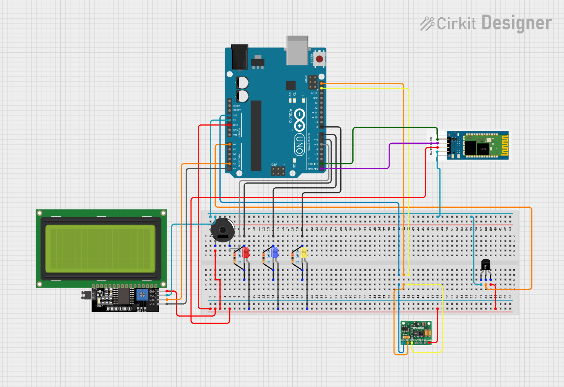
Circuit Documentation
Summary
This circuit integrates various components with an Arduino UNO microcontroller to perform multiple functions. It includes temperature sensing, pulse oximetry, Bluetooth communication, visual output through LEDs and an LCD display, and audio signaling with a piezo buzzer. The circuit is designed to monitor environmental and physiological parameters, display data, and communicate wirelessly.
Component List
Microcontroller
- Arduino UNO: A microcontroller board based on the ATmega328P. It has digital input/output pins, analog inputs, a USB connection for programming, and power management features.
Sensors
- Temperature Sensor (LM35): An analog temperature sensor that provides a voltage output proportional to the ambient temperature.
- Max30100: A sensor module that combines a pulse oximeter and heart-rate monitor.
Communication Module
- HC-06: A Bluetooth module that allows for wireless communication.
Display
- LCD Display 20x4 I2C: A 20x4 character LCD display with an I2C interface for displaying text and numbers.
Indicators
- LED: Two Pin (red)
- LED: Two Pin (blue)
- LED: Two Pin (yellow): LEDs of different colors used as visual indicators.
Passive Components
- Resistor: Three resistors with a resistance of 220 Ohms, used to limit current through the LEDs.
Audio
- Piezo Buzzer: An electronic device that emits sound when an electric signal is applied.
Wiring Details
Arduino UNO
- GND: Connected to the ground pins of all components.
- 3.3V: Powers the Max30100 sensor.
- 5V: Powers the Temperature Sensor (LM35), LCD Display, and HC-06 Bluetooth module.
- A0: Receives the analog output from the Temperature Sensor (LM35).
- A4 (SDA): I2C data line connected to the SDA pins of the Max30100 sensor and LCD Display.
- A5 (SCL): I2C clock line connected to the SCL pins of the Max30100 sensor and LCD Display.
- D0 (RX): Receives data from the TXD pin of the HC-06 Bluetooth module.
- D1 (TX): Sends data to the RXD pin of the HC-06 Bluetooth module.
- D5: Connected to the Piezo Buzzer.
- D6, D7, D8: Connected to the anodes of the red, blue, and yellow LEDs through 220 Ohm resistors, respectively.
Temperature Sensor (LM35)
- +Vs: Powered by the 5V output from the Arduino UNO.
- Vout: Connected to the A0 analog input on the Arduino UNO.
- GND: Connected to the ground.
Max30100
- VIN: Powered by the 3.3V output from the Arduino UNO.
- SCL: Connected to the A5 (SCL) pin on the Arduino UNO.
- SDA: Connected to the A4 (SDA) pin on the Arduino UNO.
- GND: Connected to the ground.
LCD Display 20x4 I2C
- VCC: Powered by the 5V output from the Arduino UNO.
- SCL: Connected to the A5 (SCL) pin on the Arduino UNO.
- SDA: Connected to the A4 (SDA) pin on the Arduino UNO.
- GND: Connected to the ground.
LEDs (Red, Blue, Yellow)
- Anode: Connected to the D6, D7, and D8 pins on the Arduino UNO through 220 Ohm resistors, respectively.
- Cathode: Connected to the ground.
Resistor
- Pin1: Connected to the D6, D7, and D8 pins on the Arduino UNO.
- Pin2: Connected to the anodes of the red, blue, and yellow LEDs, respectively.
HC-06 Bluetooth Module
- VCC: Powered by the 5V output from the Arduino UNO.
- RXD: Connected to the D1 (TX) pin on the Arduino UNO.
- TXD: Connected to the D0 (RX) pin on the Arduino UNO.
- GND: Connected to the ground.
Piezo Buzzer
- Pin 1: Connected to the D5 pin on the Arduino UNO.
- Pin 2: Connected to the ground.
Documented Code
Arduino UNO Code (sketch.ino)
void setup() {
  // put your setup code here, to run once:

}

void loop() {
  // put your main code here, to run repeatedly:

}
This code template provides the basic structure for an Arduino sketch with setup() and loop() functions. The setup() function is intended for initialization code that runs once, while the loop() function contains code that runs repeatedly, forming the main logic of the program. The actual implementation details need to be filled in based on the specific requirements of the circuit's functionality.