
ESP32-Based Wi-Fi Controlled LED and Keypad Interface with LCD Display
View and Edit Project In Cirkit Designer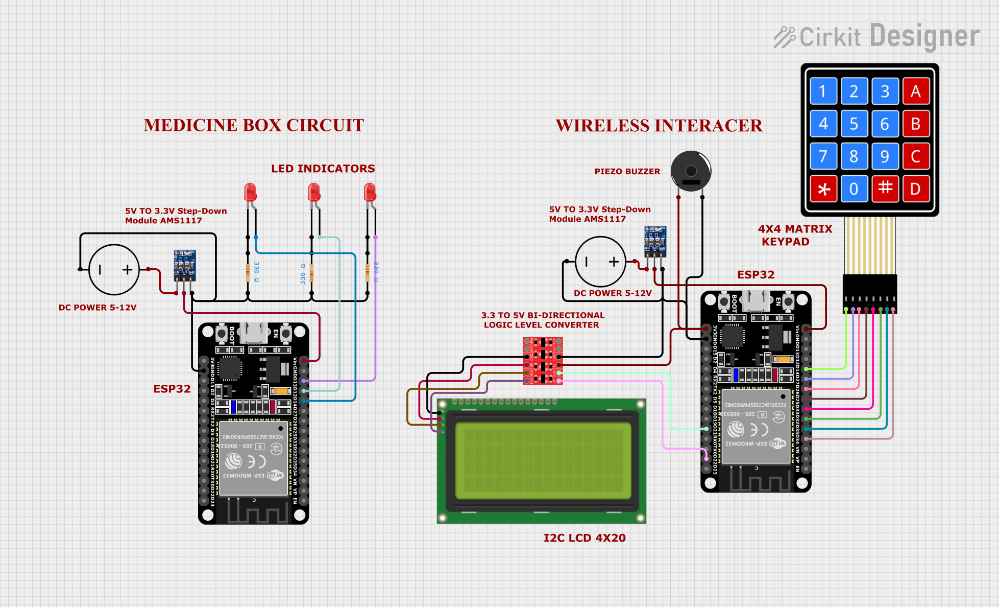
Circuit Documentation
Summary
This document provides a detailed overview of a circuit that includes an ESP32 microcontroller, LEDs, resistors, a 4x4 membrane matrix keypad, a piezo buzzer, a bi-directional logic level converter, an LCD display, and power management components. The circuit is designed to interface various input and output devices with the ESP32, providing a comprehensive example of embedded system design.
Component List
ESP32 (30 pin)
- Description: A powerful microcontroller with built-in Wi-Fi and Bluetooth capabilities.
- Pins: EN, VP, VN, D34, D35, D32, D33, D25, D26, D27, D14, D12, D13, GND, Vin, D23, D22, TX0, RX0, D21, D19, D18, D5, TX2, RX2, D4, D2, D15, 3V3
DC Power Source
- Description: Provides the necessary power for the circuit.
- Pins: Ground, Positive
ams1117 3.3
- Description: A voltage regulator that steps down the voltage to 3.3V.
- Pins: VIN, OUT, GND
LED: Two Pin (red)
- Description: A red LED used for visual indication.
- Pins: cathode, anode
Resistor
- Description: A resistor with a resistance of 330 Ohms.
- Pins: pin1, pin2
- Properties: Resistance = 330 Ohms
4X4 Membrane Matrix Keypad
- Description: A keypad with 4 rows and 4 columns.
- Pins: R1, R2, R3, R4, C1, C2, C3, C4
Lcd 20x4 i2c
- Description: A 20x4 character LCD display with I2C interface.
- Pins: GND, 5v, SCA, SCL
Bi-Directional Logic Level Converter
- Description: Converts voltage levels between different parts of the circuit.
- Pins: HV1, HV2, HV, GND, HV3, HV4, LV1, LV2, LV, LV3, LV4
Piezo Buzzer
- Description: A piezoelectric buzzer for sound output.
- Pins: pin 1, pin 2
Wiring Details
ESP32 (30 pin)
- D14 connected to anode of LED: Two Pin (red)
- D12 connected to anode of LED: Two Pin (red)
- D13 connected to anode of LED: Two Pin (red)
- Vin connected to OUT of ams1117 3.3
- GND connected to:
- pin2 of Resistor
- Ground of DC Power Source
- GND of ams1117 3.3
- D34 connected to C4 of 4X4 Membrane Matrix Keypad
- D35 connected to C3 of 4X4 Membrane Matrix Keypad
- D32 connected to C2 of 4X4 Membrane Matrix Keypad
- D33 connected to C1 of 4X4 Membrane Matrix Keypad
- D25 connected to R4 of 4X4 Membrane Matrix Keypad
- D26 connected to R3 of 4X4 Membrane Matrix Keypad
- D27 connected to R2 of 4X4 Membrane Matrix Keypad
- D14 connected to R1 of 4X4 Membrane Matrix Keypad
- Vin connected to OUT of ams1117 3.3
- D22 connected to LV1 of Bi-Directional Logic Level Converter
- D21 connected to LV2 of Bi-Directional Logic Level Converter
- GND connected to:
- Ground of DC Power Source
- pin 2 of Piezo Buzzer
- GND of Bi-Directional Logic Level Converter
- GND of ams1117 3.3
- 3V3 connected to LV of Bi-Directional Logic Level Converter
DC Power Source
- Ground connected to:
- pin2 of Resistor
- GND of ESP32 (30 pin)
- GND of ams1117 3.3
- Positive connected to VIN of ams1117 3.3
ams1117 3.3
- VIN connected to Positive of DC Power Source
- OUT connected to Vin of ESP32 (30 pin)
- GND connected to:
- Ground of DC Power Source
- GND of ESP32 (30 pin)
LED: Two Pin (red)
- anode connected to:
- D14 of ESP32 (30 pin)
- D12 of ESP32 (30 pin)
- D13 of ESP32 (30 pin)
- cathode connected to:
- pin1 of Resistor
- pin2 of Resistor
- pin1 of Resistor
Resistor
- pin1 connected to:
- cathode of LED: Two Pin (red)
- cathode of LED: Two Pin (red)
- cathode of LED: Two Pin (red)
- pin2 connected to:
- Ground of DC Power Source
- GND of ESP32 (30 pin)
- GND of ams1117 3.3
4X4 Membrane Matrix Keypad
- C4 connected to D34 of ESP32 (30 pin)
- C3 connected to D35 of ESP32 (30 pin)
- C2 connected to D32 of ESP32 (30 pin)
- C1 connected to D33 of ESP32 (30 pin)
- R4 connected to D25 of ESP32 (30 pin)
- R3 connected to D26 of ESP32 (30 pin)
- R2 connected to D27 of ESP32 (30 pin)
- R1 connected to D14 of ESP32 (30 pin)
Lcd 20x4 i2c
- GND connected to GND of Bi-Directional Logic Level Converter
- 5v connected to HV of Bi-Directional Logic Level Converter
- SCA connected to HV2 of Bi-Directional Logic Level Converter
- SCL connected to HV1 of Bi-Directional Logic Level Converter
Bi-Directional Logic Level Converter
- LV1 connected to D22 of ESP32 (30 pin)
- LV2 connected to D21 of ESP32 (30 pin)
- GND connected to:
- Ground of DC Power Source
- GND of ams1117 3.3
- GND of ESP32 (30 pin)
- LV connected to 3V3 of ESP32 (30 pin)
- HV connected to 5v of Lcd 20x4 i2c
- HV2 connected to SCA of Lcd 20x4 i2c
- HV1 connected to SCL of Lcd 20x4 i2c
Piezo Buzzer
- pin 1 connected to LV of Bi-Directional Logic Level Converter
- pin 2 connected to Ground of DC Power Source
Code
No code is provided for this circuit.
This document provides a comprehensive overview of the circuit, including a detailed component list and wiring details. The circuit integrates various input and output devices with the ESP32 microcontroller, demonstrating a practical application of embedded system design.