
Raspberry Pi and Cytron Motor Driver Controlled 12V Geared Motor System
View and Edit Project In Cirkit Designer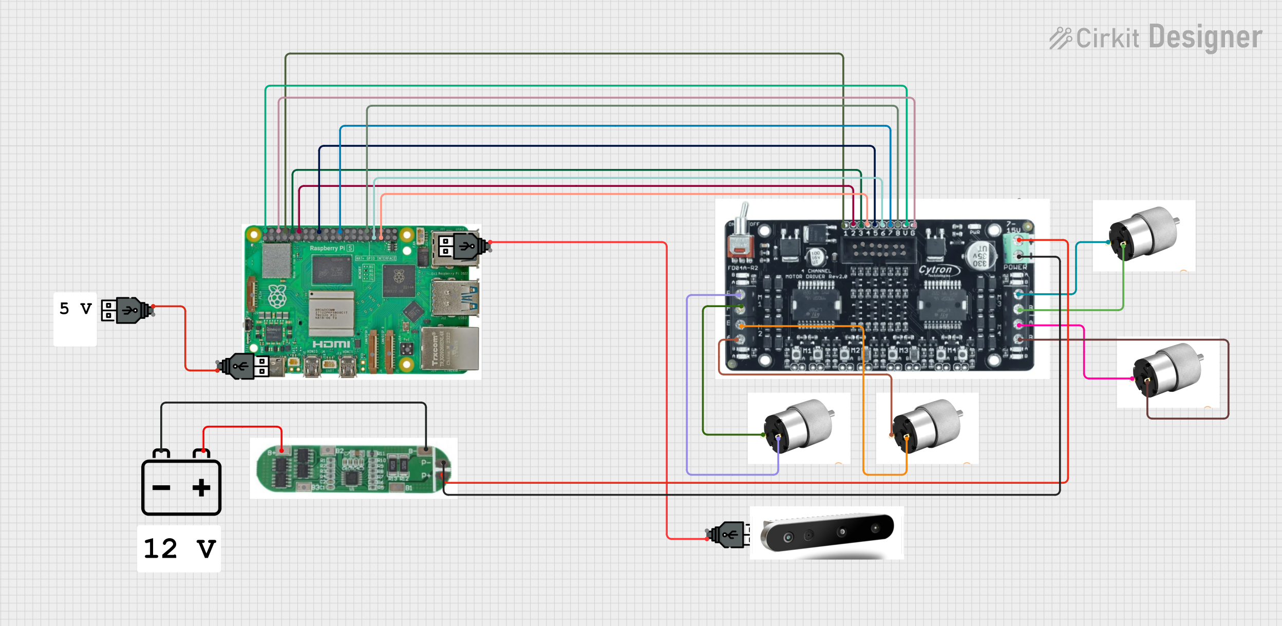
Circuit Documentation
Summary
This document provides a detailed overview of a circuit designed to control multiple 12V geared motors using a Raspberry Pi 5 and Cytron FD04A 4-Channel Motor Drivers. The circuit also includes a 12V battery, a Battery Management System (BMS), and USB power supplies. The Raspberry Pi 5 is used to control the motor drivers, which in turn control the motors. The BMS is used to manage the battery, ensuring safe operation.
Component List
Cytron FD04A 4-Channel Motor Driver
- Description: Motor driver capable of controlling up to four motors.
- Pins: Motor 1 direction, Motor 1 enable/Speed Control, Motor 2 Direction, Motor 2 enable/Speed Control, Motor 3 enable/Speed Control, Motor 4 enable/Speed Control, Motor 3 direction, Motor 4 direction, Output voltage 5 V, Ground, Motor 1 Output A, Motor 1 Output B, Motor 2 Output A, Motor 2 Output B, Motor 3 Output A, Motor 3 Output B, Motor 4 Output A, Motor 4 Output B, power +, power -
12V Geared Motor
- Description: Geared motor operating at 12V.
- Pins: Terminal 1, Terminal 2
Raspberry Pi 5
- Description: Single-board computer used for controlling the motor drivers.
- Pins: Type-C, Micro HDMI 1, Micro HDMI 2, Camera 1, Camera 2, PoE, Fan, PCIe, USB 3.0, USB 2.0, Ethernet, 5V, GND, 3.3v, GPIO 14, GPIO 15, GPIO 18, GPIO 23, GPIO 24, GPIO 25, GPIO 8, GPIO 7, GPIO 1, GPIO 12, GPIO 16, GPIO 20, GPIO 21, GPIO 2, GPIO 3, GPIO 4, GPIO 17, GPIO 27, GPIO 22, GPIO 10, GPIO 9, GPIO 11, GPIO 0, GPIO 5, GPIO 6, GPIO 13, GPIO 19, GPIO 26
12V Battery
- Description: Power source for the circuit.
- Pins: -, +
USB Power
- Description: USB power supply.
- Pins: +, -
Depth Camera
- Description: Camera for depth sensing.
- Pins: USB
Battery Management System (BMS)
- Description: Manages the battery to ensure safe operation.
- Pins: B+, B2, B-, P-, P+, B3, B1
Wiring Details
Cytron FD04A 4-Channel Motor Driver
- Output voltage 5 V connected to 5V on Raspberry Pi 5
- Ground connected to GND on Raspberry Pi 5
- Motor 1 direction connected to GPIO 14 on Raspberry Pi 5
- Motor 2 Direction connected to GPIO 15 on Raspberry Pi 5
- Motor 1 enable/Speed Control connected to GPIO 18 on Raspberry Pi 5
- Motor 3 direction connected to GPIO 24 on Raspberry Pi 5
- Motor 4 direction connected to GPIO 8 on Raspberry Pi 5
- Motor 4 enable/Speed Control connected to GPIO 12 on Raspberry Pi 5
- Motor 3 enable/Speed Control connected to GPIO 13 on Raspberry Pi 5
- Motor 2 enable/Speed Control connected to GPIO 19 on Raspberry Pi 5
- Motor 1 Output A connected to Terminal 1 on 12V Geared Motor
- Motor 1 Output B connected to Terminal 2 on 12V Geared Motor
- Motor 2 Output A connected to Terminal 1 on 12V Geared Motor
- Motor 2 Output B connected to Terminal 2 on 12V Geared Motor
- Motor 3 Output A connected to Terminal 1 on 12V Geared Motor
- Motor 3 Output B connected to Terminal 2 on 12V Geared Motor
- Motor 4 Output A connected to Terminal 1 on 12V Geared Motor
- Motor 4 Output B connected to Terminal 2 on 12V Geared Motor
- power - connected to P- on BMS
- power + connected to P+ on BMS
12V Geared Motor
- Terminal 1 connected to Motor 1 Output A on Cytron FD04A 4-Channel Motor Driver
- Terminal 2 connected to Motor 1 Output B on Cytron FD04A 4-Channel Motor Driver
Raspberry Pi 5
- 5V connected to Output voltage 5 V on Cytron FD04A 4-Channel Motor Driver
- GND connected to Ground on Cytron FD04A 4-Channel Motor Driver
- GPIO 14 connected to Motor 1 direction on Cytron FD04A 4-Channel Motor Driver
- GPIO 15 connected to Motor 2 Direction on Cytron FD04A 4-Channel Motor Driver
- GPIO 18 connected to Motor 1 enable/Speed Control on Cytron FD04A 4-Channel Motor Driver
- GPIO 24 connected to Motor 3 direction on Cytron FD04A 4-Channel Motor Driver
- GPIO 8 connected to Motor 4 direction on Cytron FD04A 4-Channel Motor Driver
- GPIO 12 connected to Motor 4 enable/Speed Control on Cytron FD04A 4-Channel Motor Driver
- GPIO 13 connected to Motor 3 enable/Speed Control on Cytron FD04A 4-Channel Motor Driver
- GPIO 19 connected to Motor 2 enable/Speed Control on Cytron FD04A 4-Channel Motor Driver
12V Battery
- - connected to B- on BMS
- + connected to B+ on BMS
USB Power
- + connected to + on another USB Power
Battery Management System (BMS)
- B- connected to - on 12V Battery
- B+ connected to + on 12V Battery
- P- connected to power - on Cytron FD04A 4-Channel Motor Driver
- P+ connected to power + on Cytron FD04A 4-Channel Motor Driver
Code
No code is provided for this circuit.
This document provides a comprehensive overview of the circuit, including a summary, component list, wiring details, and code documentation. The wiring details section ensures that each component's connections are clearly outlined, facilitating easy assembly and troubleshooting.