
Circuit Documentation
Summary of the Circuit
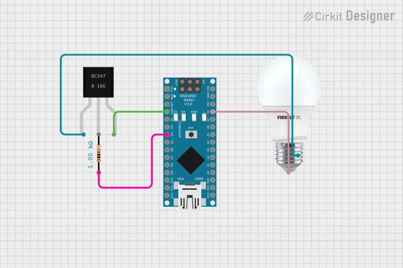
This circuit appears to be a simple control circuit utilizing an Arduino Nano to potentially control the brightness or on/off state of a bulb. The bulb's circuit is controlled by a bc547 transistor acting as a switch or amplifier, which is in turn controlled by the Arduino Nano through one of its digital pins (D4). A resistor is included in the circuit, likely to limit the current to the base of the transistor to protect it from excessive current.
Component List
Arduino Nano
- Description: A small, breadboard-friendly microcontroller board based on the ATmega328P.
- Pins: D1/TX, D0/RX, RESET, GND, D2, D3, D4, D5, D6, D7, D8, D9, D10, D11/MOSI, D12/MISO, VIN, 5V, A7, A6, A5, A4, A3, A2, A1, A0, AREF, 3V3, D13/SCK
BULB
- Description: A simple light bulb with two terminals: positive and negative.
- Pins: +, -
bc547
- Description: A general-purpose NPN bipolar junction transistor (BJT) used for switching and amplification.
- Pins: Collector, Base, Emitter
Resistor
- Description: A passive two-terminal electrical component that implements electrical resistance as a circuit element.
- Resistance: 1000 Ohms
- Pins: pin1, pin2
Wiring Details
Arduino Nano
- GND connected to bc547 Emitter
- D4 connected to Resistor pin1
- 5V connected to BULB +
BULB
- + connected to Arduino Nano 5V
- - connected to bc547 Collector
bc547
- Collector connected to BULB -
- Base connected to Resistor pin2 (implied connection, not explicitly stated in the net list)
- Emitter connected to Arduino Nano GND
Resistor
- pin1 connected to Arduino Nano D4
- pin2 connected to bc547 Base (implied connection, not explicitly stated in the net list)
Documented Code
sketch.ino
void setup() {
  // put your setup code here, to run once:

}

void loop() {
  // put your main code here, to run repeatedly:

}
documentation.txt
The provided code is a template with empty setup() and loop() functions. The actual implementation should control the digital output on pin D4 to switch the transistor on and off, thereby controlling the bulb. The code should be written to set pin D4 as an output in the setup() function and then to toggle this pin or apply PWM (Pulse Width Modulation) in the loop() function to control the bulb's state or brightness.
Note: The wiring details for the bc547 Base are assumed based on typical usage and the components involved. The actual electrical net list provided does not specify the connection for the Base pin, which is essential for the transistor to operate correctly.