Cirkit Designer
Your all-in-one circuit design IDE
Home /
Project Documentation
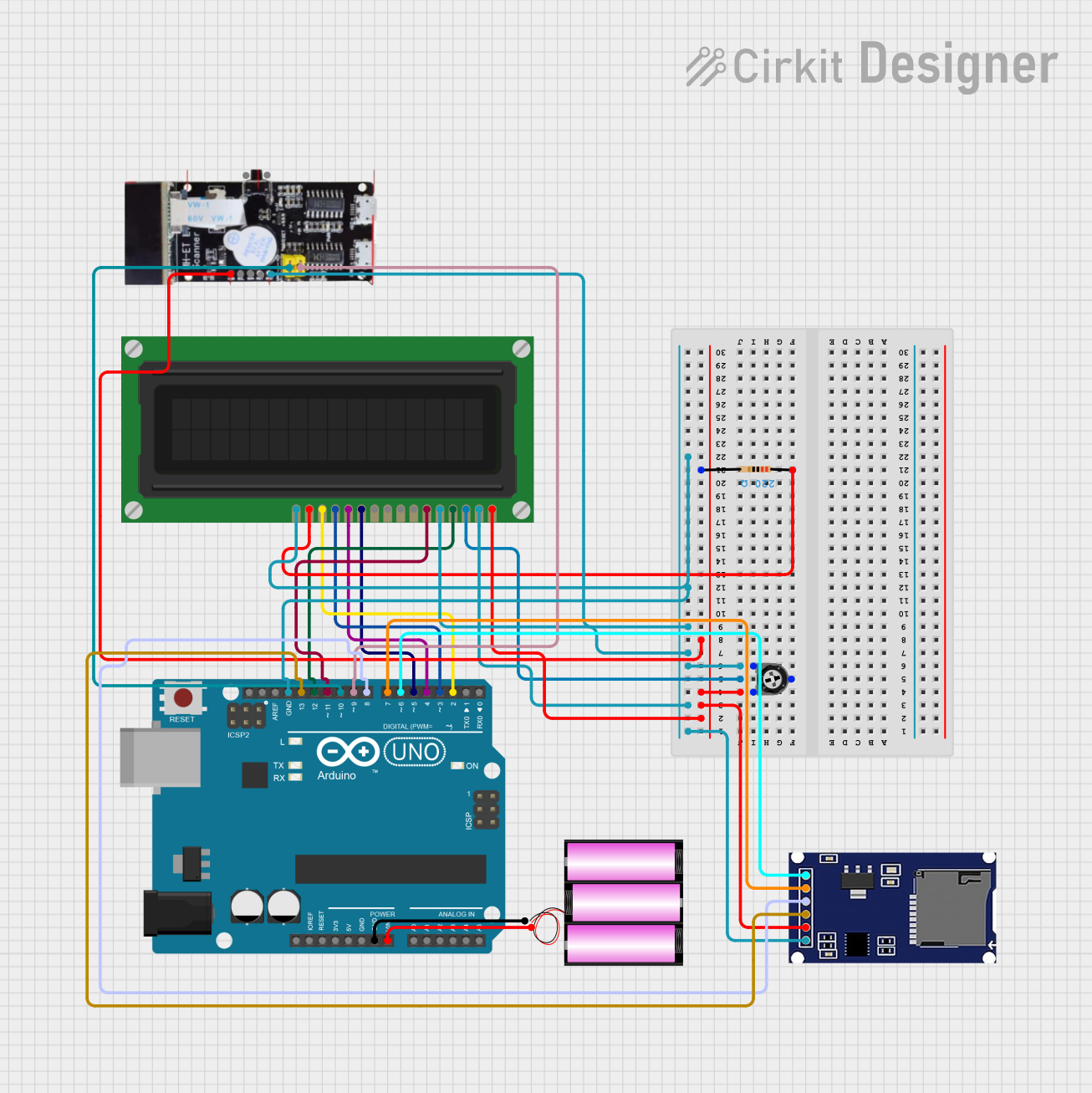
Arduino UNO-Based Barcode Scanner with LCD Display and SD Card Storage
Circuit Documentation
Summary
This document provides a detailed overview of a circuit that includes an Arduino UNO microcontroller, a 12V battery, a barcode scanner, an LCD display, a resistor, a trimmer potentiometer, and an SD module. The circuit is designed to interface these components for various functionalities, including display and data storage.
Component List
Arduino UNO
- Description: A microcontroller board based on the ATmega328P.
- Pins: UNUSED, IOREF, Reset, 3.3V, 5V, GND, Vin, A0, A1, A2, A3, A4, A5, SCL, SDA, AREF, D13, D12, D11, D10, D9, D8, D7, D6, D5, D4, D3, D2, D1, D0
Battery 12V
- Description: A 12V power source.
- Pins: +, -
Barcode Scanner
- Description: A device used to scan barcodes.
- Pins: VDD, SCL, SDA, RST, GND, SW, SRX, STX
LCD Display (16 pin)
- Description: A 16-pin LCD display for visual output.
- Pins: VSS, VDD, VO, RS, R_W, E, DB0, DB1, DB2, DB3, DB4, DB5, DB6, DB7, A, K
Resistor
- Description: A 220 Ohm resistor.
- Pins: pin1, pin2
- Properties: Resistance: 220 Ohms
Trimmer Potentiometer
- Description: A 10k Ohm trimmer potentiometer.
- Pins: leg1, wiper, leg2
- Properties: Resistance: 10k Ohms
SD Module
- Description: A module for interfacing with SD cards.
- Pins: CS, SCK, MOSI, MISO, VCC, GND
Wiring Details
Arduino UNO
- GND: Connected to GND of the battery, SD module, LCD display (VDD, R_W, K), and barcode scanner.
- Vin: Connected to + of the battery.
- D13: Connected to MISO of the SD module.
- D12: Connected to RS of the LCD display.
- D11: Connected to E of the LCD display.
- D10: Connected to SRX of the barcode scanner.
- D9: Connected to STX of the barcode scanner.
- D8: Connected to MOSI of the SD module.
- D7: Connected to SCK of the SD module.
- D6: Connected to CS of the SD module.
- D5: Connected to DB4 of the LCD display.
- D4: Connected to DB5 of the LCD display.
- D3: Connected to DB6 of the LCD display.
- D2: Connected to DB7 of the LCD display.
Battery 12V
- -: Connected to GND of the Arduino UNO.
- +: Connected to Vin of the Arduino UNO.
Barcode Scanner
- VDD: Connected to leg2 of the trimmer potentiometer.
- GND: Connected to GND of the Arduino UNO.
- SRX: Connected to D10 of the Arduino UNO.
- STX: Connected to D9 of the Arduino UNO.
LCD Display (16 pin)
- VSS: Connected to leg2 of the trimmer potentiometer.
- VDD: Connected to leg1 of the trimmer potentiometer.
- VO: Connected to wiper of the trimmer potentiometer.
- RS: Connected to D12 of the Arduino UNO.
- R_W: Connected to leg1 of the trimmer potentiometer.
- E: Connected to D11 of the Arduino UNO.
- DB4: Connected to D5 of the Arduino UNO.
- DB5: Connected to D4 of the Arduino UNO.
- DB6: Connected to D3 of the Arduino UNO.
- DB7: Connected to D2 of the Arduino UNO.
- A: Connected to pin1 of the resistor.
- K: Connected to GND of the Arduino UNO.
Resistor
- pin1: Connected to A of the LCD display.
- pin2: Connected to leg2 of the trimmer potentiometer.
Trimmer Potentiometer
- leg1: Connected to GND of the SD module and VDD, R_W of the LCD display.
- wiper: Connected to VO of the LCD display.
- leg2: Connected to VSS of the LCD display, VCC of the SD module, and VDD of the barcode scanner.
SD Module
- CS: Connected to D6 of the Arduino UNO.
- SCK: Connected to D7 of the Arduino UNO.
- MOSI: Connected to D8 of the Arduino UNO.
- MISO: Connected to D13 of the Arduino UNO.
- VCC: Connected to leg2 of the trimmer potentiometer.
- GND: Connected to leg1 of the trimmer potentiometer.
Documented Code
Arduino UNO Code (sketch.ino)
void setup() {
  // put your setup code here, to run once:

}

void loop() {
  // put your main code here, to run repeatedly:

}
Documentation (documentation.txt)
This document provides a comprehensive overview of the circuit, including the components used, their wiring details, and the code for the Arduino UNO microcontroller.