
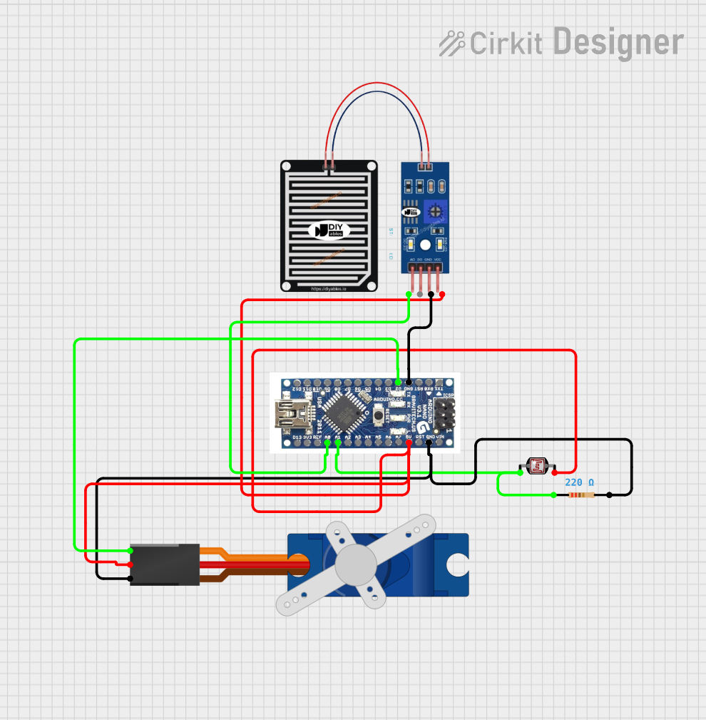
Circuit Documentation
Summary
The circuit in question is designed to interface a rain sensor and a photocell (LDR) with an Arduino Nano microcontroller, and to control a Tower Pro SG90 servo motor based on the inputs from these sensors. The rain sensor is used to detect the presence of rain by measuring the analog voltage level on its output pin, which is connected to an analog input on the Arduino Nano. The photocell, in conjunction with a resistor, forms a voltage divider that provides a variable voltage to another analog input on the Arduino Nano, indicative of the light level. The servo motor is controlled by a digital output from the Arduino Nano and is powered by the same 5V supply that powers the rain sensor and the photocell. The ground connections are shared among all components.
Component List
RAIN SENSOR
- Pins: AO, DO, GRD, VCC
- Description: A sensor that detects rain by measuring the resistance between two contacts that varies with moisture level. The analog output (AO) provides a variable voltage that can be read by a microcontroller.
Tower Pro SG90 Servo
- Pins: Signal, +5V, GND
- Description: A small and lightweight servo motor that can be precisely controlled through PWM signals on its signal pin.
Arduino Nano
- Pins: D12, D11, D10, D9, D8, D7, D6, D5, D4, D3, D2, GND, RST, RX0, TX1, D13, 3V3, REF, A0, A1, A3, A4, A5, A6, A7, 5V, VIN
- Description: A compact microcontroller board based on the ATmega328P, with digital and analog I/O pins.
Photocell (LDR)
- Pins: pin 0, pin 1
- Description: A light-dependent resistor whose resistance changes with the intensity of light falling on it, used to measure light levels.
Resistor
- Pins: pin1, pin2
- Resistance: 220 Ohms
- Description: A fixed-value resistor used to limit current or divide voltages within the circuit.
Wiring Details
RAIN SENSOR
- AO (Analog Output) connected to Arduino Nano A0 (Analog Input)
- GRD connected to Arduino Nano GND (Ground)
- VCC connected to Arduino Nano 5V (5 Volts Supply)
Tower Pro SG90 Servo
- Signal connected to Arduino Nano D2 (Digital Output)
- +5V connected to Arduino Nano 5V (5 Volts Supply)
- GND connected to Arduino Nano GND (Ground)
Arduino Nano
- A0 connected to RAIN SENSOR AO (Analog Output)
- 5V connected to RAIN SENSOR VCC, Photocell (LDR) pin 1, and Tower Pro SG90 servo +5V
- GND connected to RAIN SENSOR GRD, Tower Pro SG90 servo GND, and one side of the Resistor (pin2)
- D2 connected to Tower Pro SG90 servo Signal
- A1 connected to one side of the Photocell (LDR) (pin 0)
Photocell (LDR)
- pin 0 connected to Arduino Nano A1 (Analog Input)
- pin 1 connected to Arduino Nano 5V (5 Volts Supply)
Resistor
- pin1 connected to Photocell (LDR) pin 0 and Arduino Nano A1 (Analog Input)
- pin2 connected to Arduino Nano GND (Ground)
Documented Code
No code has been provided for the microcontroller. To fully utilize this circuit, embedded code for the Arduino Nano is required to read the analog values from the rain sensor and the photocell, process these values, and generate the appropriate control signals for the servo motor. The code would typically include initialization of the I/O pins, reading the sensor inputs in the main loop, and applying logic to determine the servo position based on the sensor readings.