
Circuit Documentation
Summary
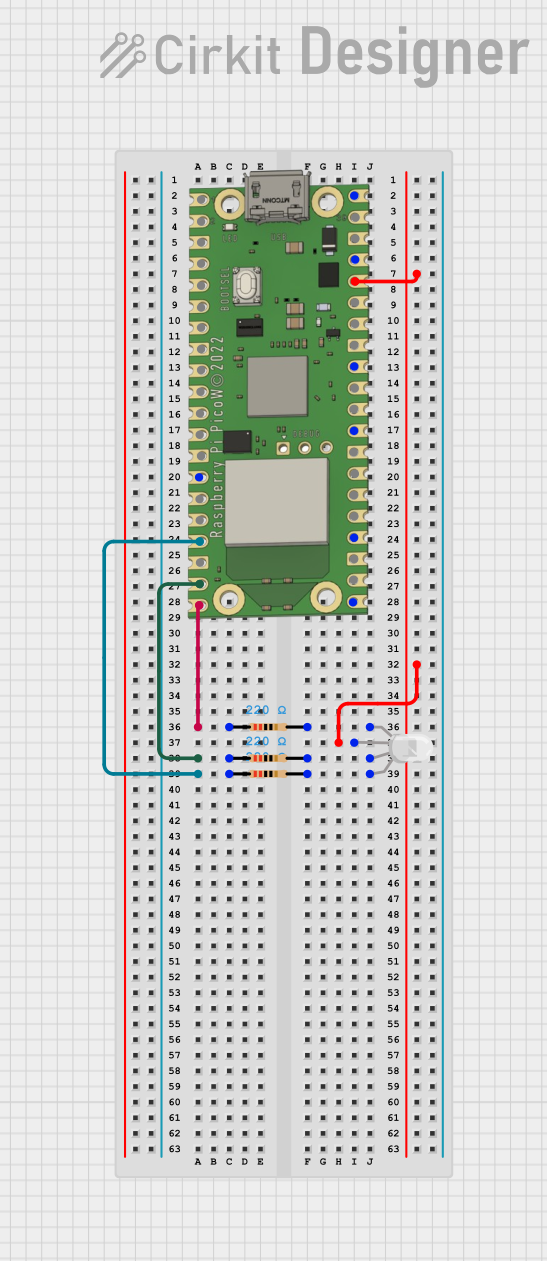
This document provides a detailed description of a circuit that includes a Raspberry Pi Pico W microcontroller, an RGB LED, and three resistors. The circuit is designed to control the RGB LED using the GPIO pins of the Raspberry Pi Pico W. Each color channel of the RGB LED is connected to a GPIO pin through a resistor to limit the current.
Component List
Raspberry Pi Pico W
- Description: A microcontroller board based on the RP2040 microcontroller chip.
- Pins: VBUS, VSYS, GP16, GP17, GND, GP18, GP19, GP20, GP21, GP22, RUN, GP26, GP27, GP28, ADC_VREF, 3V3 OUT, 3V3_EN, GP0, GP1, GP2, GP3, GP4, GP5, GP6, GP7, GP15, GP14, GP13, GP12, GP11, GP10, GP9, GP8
RGB LED (Wokwi compatible)
- Description: A common anode RGB LED with four pins.
- Pins: R, COM, G, B
Resistor (220 Ohms)
- Description: A resistor with a resistance of 220 Ohms.
- Pins: pin1, pin2
Resistor (220 Ohms)
- Description: A resistor with a resistance of 220 Ohms.
- Pins: pin1, pin2
Resistor (220 Ohms)
- Description: A resistor with a resistance of 220 Ohms.
- Pins: pin1, pin2
Wiring Details
Raspberry Pi Pico W
- 3V3 OUT is connected to COM of the RGB LED.
- GP15 is connected to pin1 of a 220 Ohm resistor.
- GP14 is connected to pin1 of a 220 Ohm resistor.
- GP13 is connected to pin1 of a 220 Ohm resistor.
RGB LED (Wokwi compatible)
- COM is connected to 3V3 OUT of the Raspberry Pi Pico W.
- R is connected to pin2 of a 220 Ohm resistor.
- G is connected to pin2 of a 220 Ohm resistor.
- B is connected to pin2 of a 220 Ohm resistor.
Resistor (220 Ohms)
- pin1 of the first resistor is connected to GP15 of the Raspberry Pi Pico W.
- pin2 of the first resistor is connected to R of the RGB LED.
Resistor (220 Ohms)
- pin1 of the second resistor is connected to GP14 of the Raspberry Pi Pico W.
- pin2 of the second resistor is connected to G of the RGB LED.
Resistor (220 Ohms)
- pin1 of the third resistor is connected to GP13 of the Raspberry Pi Pico W.
- pin2 of the third resistor is connected to B of the RGB LED.
Code
No code is provided for this circuit.